Automatic precise assembling platform for fusion target key components

An assembly platform, fusion target technology, applied in workpiece clamping devices, assembly machines, metal processing equipment, etc., can solve the problems of complex assembly process, redundant degrees of freedom, poor stability, etc., to improve assembly accuracy and efficiency, The effect of reducing system complexity, increasing rigidity and stability

Active Publication Date: 2014-04-09
HARBIN INST OF TECH
View PDF4 Cites 15 Cited by
  • Summary
  • Abstract
  • Description
  • Claims
  • Application Information

AI Technical Summary

Problems solved by technology

[0003] The purpose of the present invention is to solve the problem of using a semi-automatic assembly device for the assembly of the key parts of the existing ignition target, which has many redundant degrees of freedom, complex assembly process, complex operation, and many accumulated errors, poor rigidity, and manual participation, resulting in poor stability and low efficiency. Low problem, and provide an automatic precision assembly platform for key parts of fusion target

Method used


Image

  • Automatic precise assembling platform for fusion target key components
  • Automatic precise assembling platform for fusion target key components
  • Automatic precise assembling platform for fusion target key components

Examples


specific Embodiment approach 1

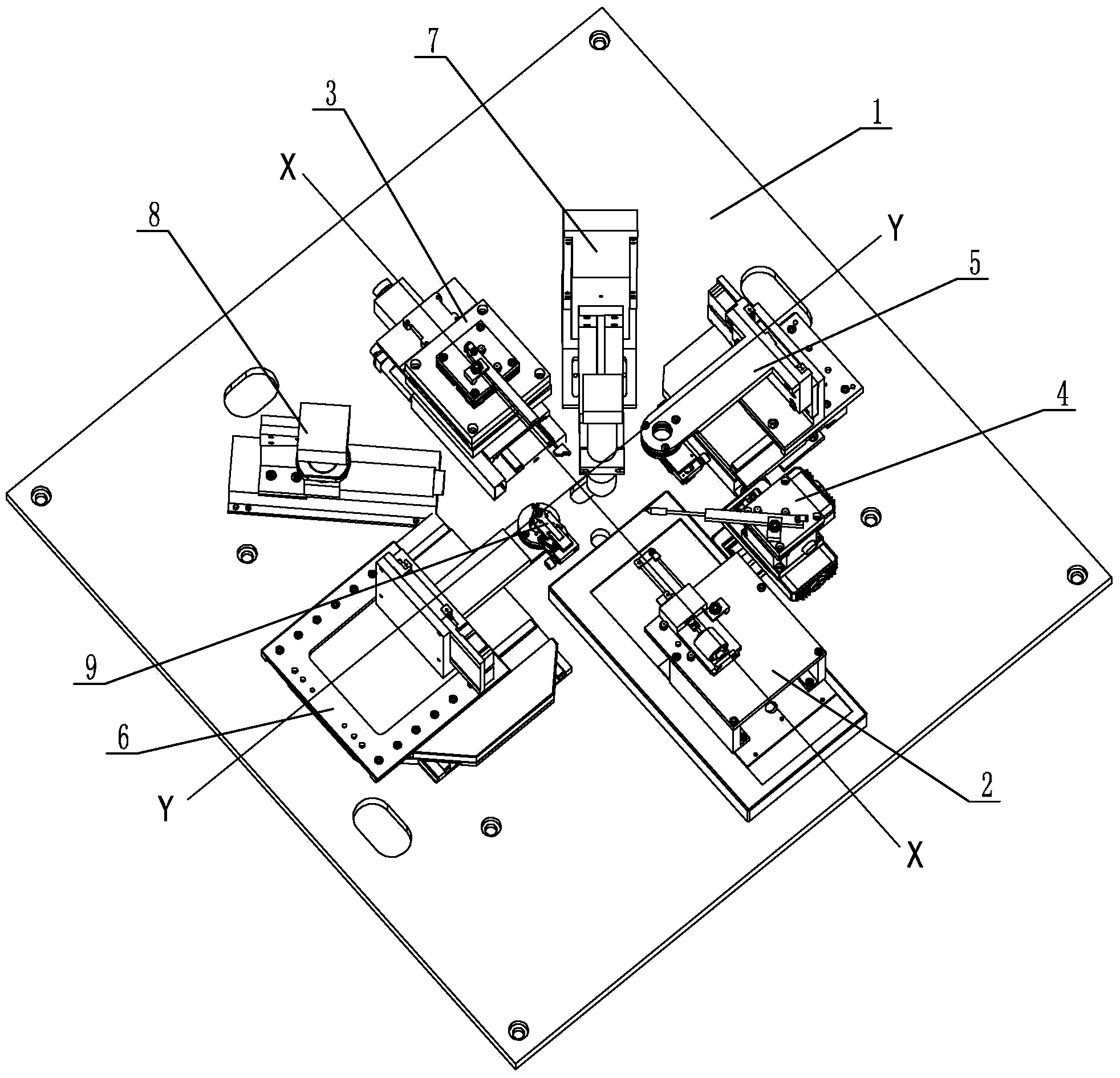
[0026] Embodiment 1: Combining figure 1 , Figure 16 and Figure 17 This embodiment is described. The automatic precision assembly platform for the key parts of fusion targets in this embodiment includes a substrate 1, a diagnostic ring preliminary positioning and clamping device 2, a diagnostic ring precise positioning and clamping device 3, a target pellet clamping and positioning device 4, and an upper set clamp. Holding and positioning device 5, lower kit clamping and positioning device 6, vertical microscope image feedback device 7 and horizontal microscope image feedback device 8, diagnostic ring preliminary positioning and clamping device 2, target pellet clamping and positioning device 4, upper kit clamping and positioning The device 5, the vertical microscope image feedback device 7, the diagnostic ring fine positioning and clamping device 3, the horizontal microscope image feedback device 8 and the lower set clamping and positioning device 6 are arranged on the uppe...

specific Embodiment approach 2

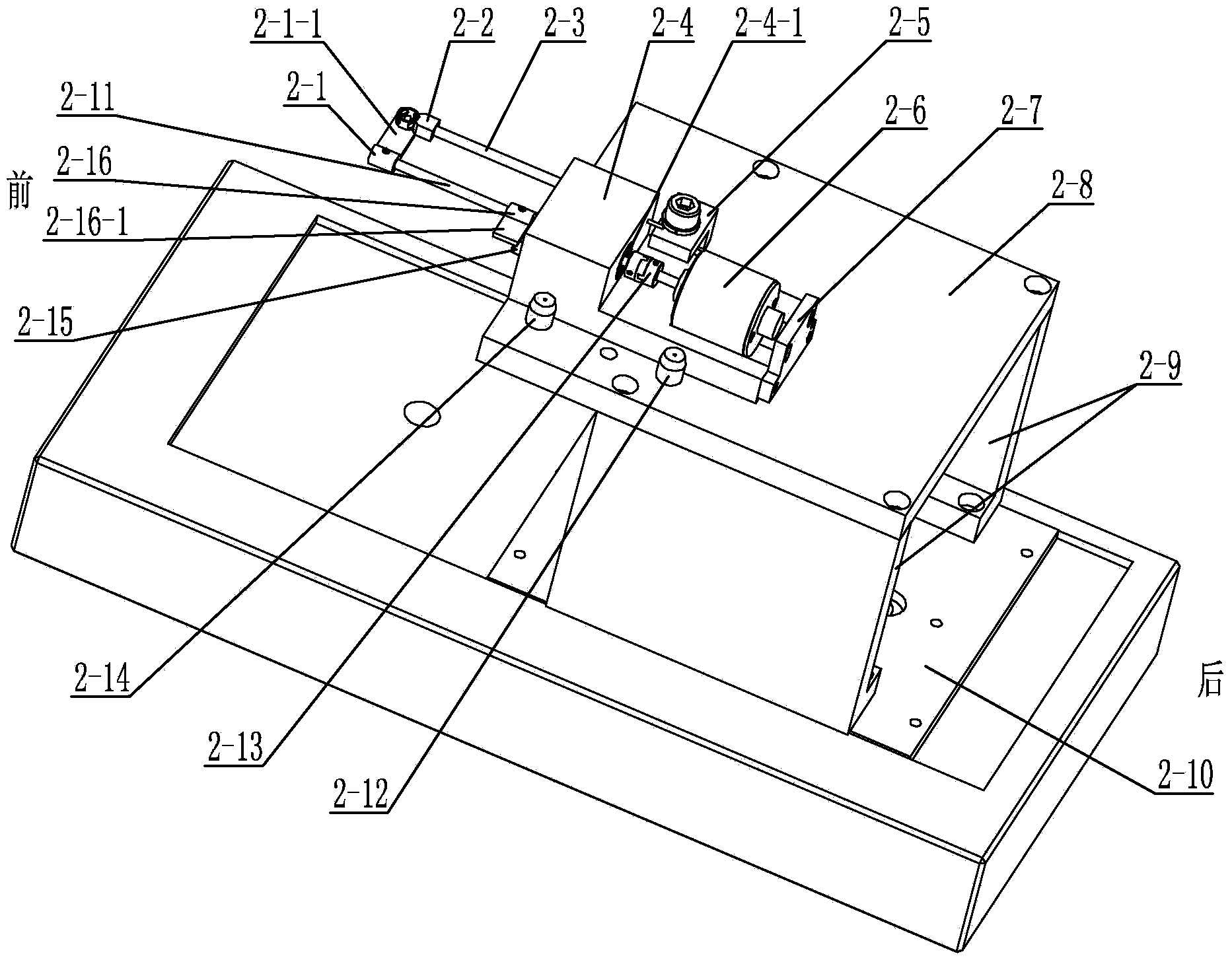
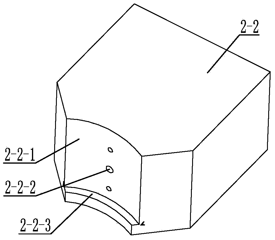
[0027] Specific implementation mode 2: Combining figure 2 and image 3Describing this embodiment, the diagnostic ring preliminary positioning and clamping device 2 of this embodiment includes a target pellet support 2-1, a preliminary positioning and clamping tip 2-2, an preliminary positioning pipette 2-3, an preliminary positioning block 2-4, Initial positioning L-shaped pressure block 2-5, rotating electromagnet 2-6, baffle plate 2-7, horizontal end plate 2-8, two L-shaped plates 2-9, initial positioning linear motor 2-10, rotating rod 2 -11, the first locating pin 2-12, the adapter 2-13, the second locating pin 2-14, the third locating pin 2-15 and the rotating positioning piece 2-16, the two L-shaped plates 2-9 are along a straight line The longitudinal center line of the motor 2-10 is symmetrically arranged on both sides of the upper end face of the initially positioned linear motor 2-10, and the inner corners of the two L-shaped plates 2-9 are arranged oppositely, and...

specific Embodiment approach 3

[0029] Specific implementation three: combination Figure 4 and Figure 5 Describing this embodiment, the diagnostic ring precise positioning and clamping device 3 of this embodiment includes a precise positioning suction head 3-1, a fourth positioning pin 3-2, a precise positioning suction tube 3-3, a precise positioning positioning rod 3-4, a precise positioning Positioning L-shaped pressure block 3-5, fifth positioning pin 3-6, fine positioning elbow 3-7, sixth positioning pin 3-8, seventh positioning pin 3-9, fine positioning connecting plate 3-10, fine adjustment Table 3-11, upper connecting plate 3-12, precise positioning linear motor 3-13, lower connecting plate 3-14 and precise positioning stepping motor 3-15, upper connecting plate 3-12, precise positioning linear motor 3-13 and the lower connecting plate 3-14 are sequentially arranged on the upper end surface of the fine positioning stepper motor 3-15 from top to bottom. 12, the fifth positioning pin 3-6 and the se...


PUM


Abstract

The invention relates to an ignition target key component assembling platform, and discloses an automatic precise assembling platform for fusion target key components to solve the problems that a semi-automatic assembling device is adopted in the existing ignition target key component assembling, the assembling process and the operating process are complex, many added up errors exist, and the stability is poor. A diagnosis ring initial positioning and clamping device, a pellet clamping and positioning device, an upper external element clamping and positioning device, a vertical microscope image feedback device, a diagnosis ring fine positioning and clamping device, a horizontal microscope image feedback device and a lower external element clamping and positioning device are anticlockwise arranged on the upper end face of a substrate, the pellet clamping and positioning device is arranged between the diagnosis ring initial positioning and clamping device and the upper external element clamping and positioning device, the vertical microscope image feedback device is arranged between the diagnosis ring fine positioning and clamping device and the upper external element clamping and positioning device, and the horizontal microscope image feedback device is arranged between the diagnosis ring fine positioning and clamping device and the lower external element clamping and positioning device. The automatic precise assembling platform is used for assembling the fusion target key components.

Description

technical field [0001] The invention relates to an assembly platform for key parts of an ignition target, belonging to the technical field of laser fusion target assembly, in particular to an automatic precise assembly platform for key parts of a fusion target. Background technique [0002] Ignition target is a kind of laser fusion target. The key parts include: target pill, diagnostic ring, upper set arm and lower set arm. The assembly requires the target to be precisely positioned in the center of the diagnostic ring, and then connected to the diagnostic ring by the upper and lower sockets. , In order to meet the ignition requirements, long-term stability and a large number of high-precision assembly ignition target assemblies are required. At present, the key parts of the domestic ignition target are assembled by traditional manual installation, which has poor precision and low efficiency. However, the redundant degrees of freedom of foreign semi-automatic assembly device...

Claims


Application Information

Patent Timeline
Patent Type & Authority Applications(China)
IPC IPC(8): B23P21/00B25B11/02
CPCB23P21/002
Inventor 荣伟彬邹宇邢济尧王乐锋孙立宁
Owner HARBIN INST OF TECH
Why Eureka
Try Eureka