Cable-driving rope replacing mechanism

A cable-driven and rope-feeding technology, which is applied in the field of the rope-changing mechanism of the cable-driven wire rope of the astronomical telescope, to avoid damage and improve safety and reliability

Active Publication Date: 2014-04-09
DALIAN HUARUI HEAVY IND GRP CO LTD
View PDF7 Cites 8 Cited by
  • Summary
  • Abstract
  • Description
  • Claims
  • Application Information

AI Technical Summary

Problems solved by technology

This technology is only applicable to the replacement of mechanical wire ropes of closed

Method used


Image

  • Cable-driving rope replacing mechanism
  • Cable-driving rope replacing mechanism
  • Cable-driving rope replacing mechanism

Examples


Embodiment Construction

[0026] The present invention will be further described below in conjunction with drawings and embodiments.

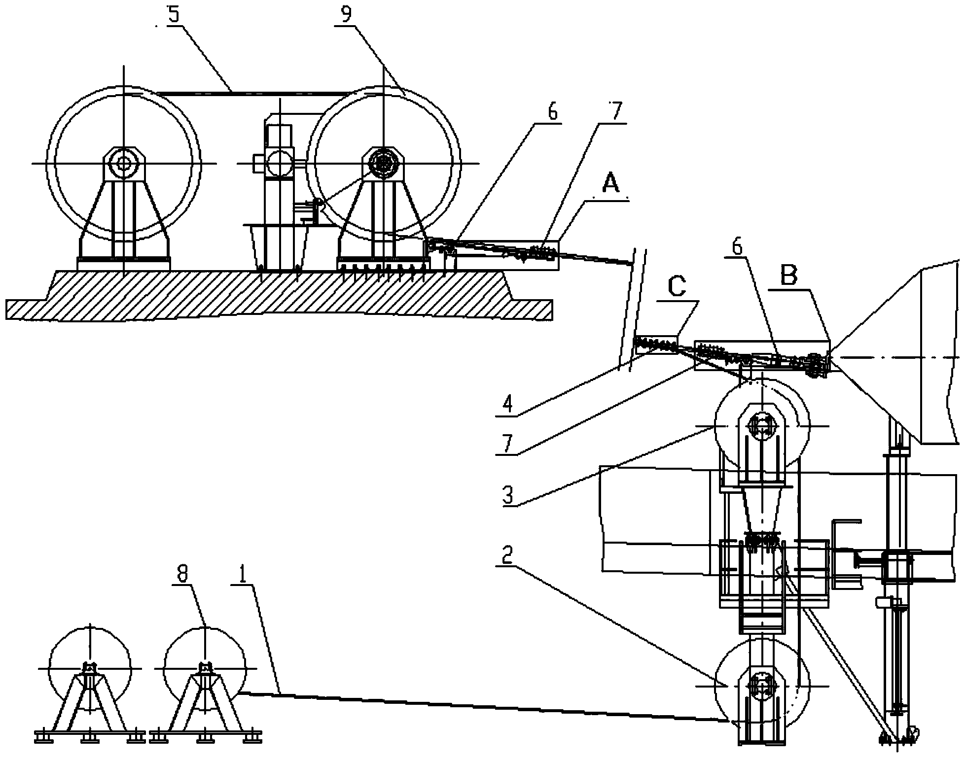
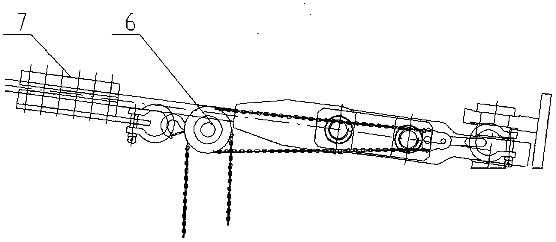
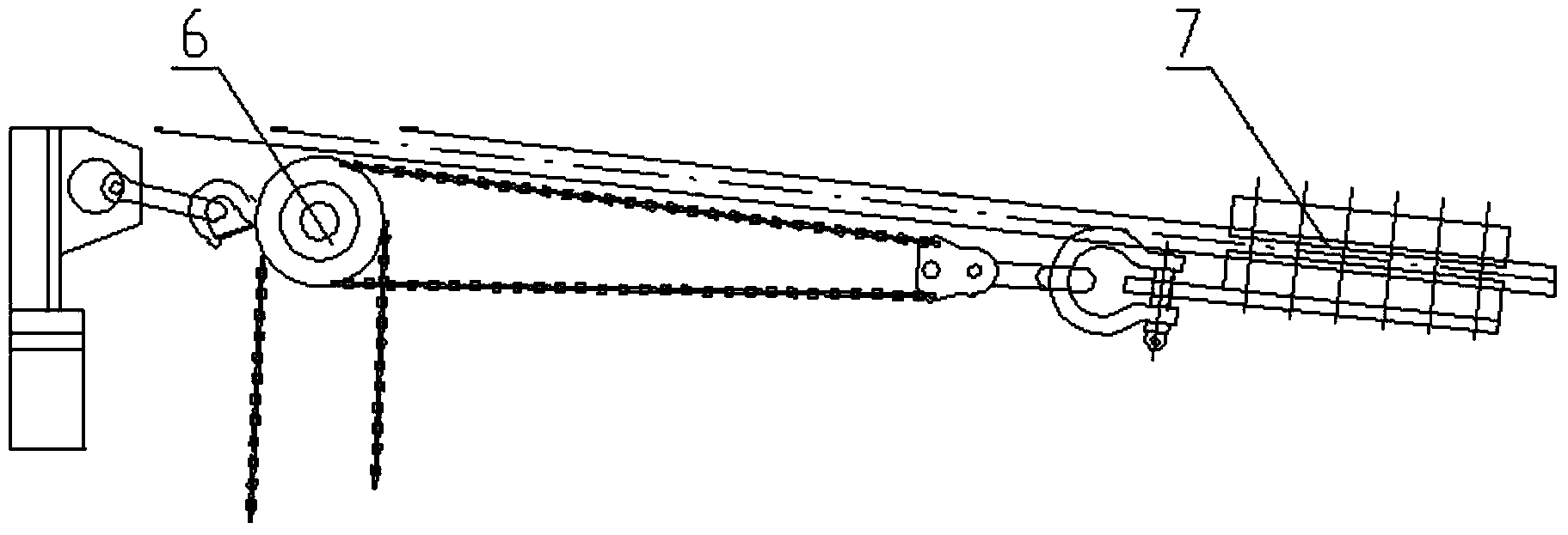
[0027] The embodiment is the signal receiving device of the telescope used in the field of astronomy—the cable changing mechanism of the cable driving the wire rope of the feed cabin. The mechanism is mainly composed of Φ26×50m process steel wire rope Ⅰ1, ground guide pulley 2, maintenance guide pulley 3, U-shaped clip 4, Φ26×650m process steel wire rope Ⅱ5, 10t chain hoist 6, rope splint 7, rope changing mechanism hoist 8, and Cooperate with the hoist 9 of the cable driving mechanism, the hoist 8 of the rope changing mechanism is arranged on the ground below the port entry platform of the cable driving part, the ground guide pulley 2 is arranged in front of the hoist 8 of the rope changing mechanism, and the maintenance guide pulley 3 is arranged on the port entry platform of the cable driving part One end of the process steel wire rope I1 bypasses the maintenance guid...


PUM


Abstract

The invention discloses a cable-driving rope replacing mechanism. A rope replacing winch is arranged beside a fixed side of a cable-driving winch rope. A ground guide pulley is arranged on ground under a cable-driving part port entering platform. A maintenance guide pulley is arranged on the cable-driving part port entering platform. One end of a first craft steel wire rope bypasses the maintenance guide pulley and the ground guide pulley and is coiled on a winch coiling block of the rope replacing mechanism, and the other end of the first craft steel wire rope is fixed at the anchoring device end of a cable-driving rope. A coiling disk of a second craft steel wire rope is placed beside a cable-driving winch. Hand pulling blocks are respectively arranged on the cable-driving winch, a rope replacing mechanism winch and the cable-driving part port entering platform. The cable-driving rope replacing mechanism has the advantages that at rope replacing time, only operation in a drive winch machine chamber on ground and the port entering platform is needed, so that risks of working aloft and damage of auxiliary parts falling off a rope to a ground part are avoided; no large hoisting equipment is needed, and only the hand pulling blocks are needed as outer force assistance, so that replacing cost is reduced; the efficiency, the safety and the reliability of rope replacement are improved.

Description

technical field [0001] The invention belongs to a rope-changing mechanism for cable machinery, in particular to a rope-changing mechanism for astronomical telescope cables driving steel wire ropes. Background technique [0002] The replacement of wire ropes of cable machinery is mostly done manually. It is relatively easy for cable machinery on the ground, but it is more difficult to replace the wire rope and the accessory parts carried on the wire rope for high-altitude cable machinery, and the maintenance is complicated and cumbersome, which is prone to falling objects. It will cause damage to the ground facilities, and the efficiency of replacing the wire rope is low, and the operation period is long. For example, the signal receiving device of the telescope used in the astronomical field—the feed cabin is driven by six wire ropes with a diameter of 46mm and a length of 617-674m, so that it moves on a spherical reflective surface with a diameter of 500m. Due to the huge ...

Claims


Application Information

Patent Timeline
IPC IPC(8): B66D1/60
Inventor 徐菁萍张金晶姜保国马洪斌王昊徐宏伟潘高峰孙才红
Owner DALIAN HUARUI HEAVY IND GRP CO LTD
Why Eureka
Try Eureka