
Melt spinning device

A melt spinning, spinning box technology, applied in melt spinning, textile and papermaking, filament/thread forming, etc., to reduce shaking and improve operability

Active Publication Date: 2017-06-20
TMT MACHINERY INC
View PDF9 Cites 0 Cited by
  • Summary
  • Abstract
  • Description
  • Claims
  • Application Information

AI Technical Summary

Problems solved by technology

Therefore, for example, the technology disclosed in Patent Document 3 cannot be applied as it is to the manufacture of high-quality long fibers with large total fineness and single filament fineness.

Method used


Image

  • Melt spinning device
  • Melt spinning device
  • Melt spinning device

Examples


Embodiment 1

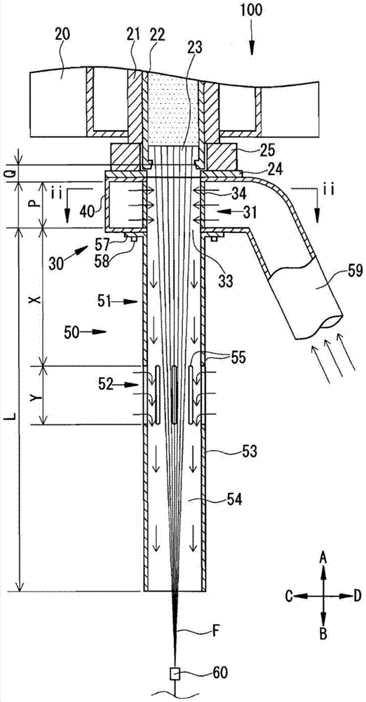
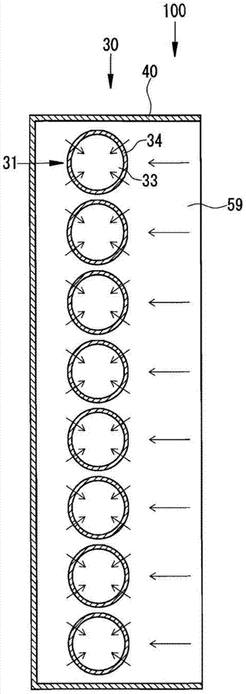
[0041] use figure 1 and figure 2The melt spinning apparatus 100 of Example 1 of the present invention will be described. In the following description, the figure 1 The direction above the diagram (arrow A) in the figure is taken as up, and the direction below the diagram (arrow B) is taken as down. exist figure 2 The side where the duct 59 is provided is defined as the rear side of the melt spinning apparatus 100 , and the opposite side is defined as the front side of the melt spinning apparatus 100 . Let the direction from the rear side to the front side (arrow C) be the first direction, and let the direction from the front side to the rear side (arrow D) be the second direction.

[0042] The melt spinning device 100 of this embodiment is a melt spinning device suitable for producing a high-quality yarn Y with a total fineness of 75 de or more and a single filament fineness of 2 dpf or more. Yarn Y with a total fineness of more than 75de and a single fiber fineness of ...

Embodiment 2

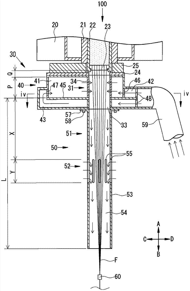
[0062] Next, use image 3 and Figure 4 The melt spinning apparatus 100 of Example 2 of the present invention will be described. The melt spinning apparatus 100 of this embodiment is different from the first embodiment in that cooling air is supplied from the front and rear of the cooling cylinder 31 . The same reference numerals are assigned to the same parts as those in Embodiment 1, and detailed description thereof will be omitted.

[0063] Such as image 3 As shown, a plurality of component housings 21 are disposed on the spinning beam 20 . A plurality of component housings 21 are arranged in a zigzag shape. A spin pack 22 is disposed in each pack case 21 , and a plurality of spinnerets 23 for spinning single fibers F are disposed at the lower end of the spin pack 22 .

[0064] The cooling device 30 mainly includes a cooling tube 31 , a cooling air supply box 40 , and an extension tube 50 . The CIQ is mainly composed of a cooling cylinder 31 and a cooling air supply ...


PUM

PropertyMeasurementUnit
lengthaaaaaaaaaa
lengthaaaaaaaaaa

Abstract

Melt spinning equipment, which can produce high-quality yarn with a total fineness of 75de or more and a single filament fineness of 2dpf or more, equipped with CIQ. Equipped with: a spinning box (20), a plurality of cooling cylinders (31) arranged below it, a cooling air supply box (40) for providing cooling air around the cooling cylinder (31), and a cooling air supply box (40) arranged in the cooling air supply box (40) ), the extension tube (50) that constitutes the second running space (54) for the single fiber group (F) to walk; the extension tube (50) is equipped with a rectifying part ( 51) and an open portion (52) formed under the rectifying portion (51) to communicate the second walking space (54) with the outside.

Description

technical field [0001] The present invention relates to the technology of a melt spinning device. More specifically, it relates to a technology of a melt spinning device capable of producing a high-quality yarn having a large total fineness and a single filament fineness. Background technique [0002] Conventionally, there is known a melt spinning apparatus for producing yarns from melted thermoplastic polymers. The melt spinning device supplies the melted thermoplastic polymer to the spin pack, and spins a plurality of single fibers (filament groups) downward from the spinneret of the spin pack. A cooling device is arranged below the spinneret to cool and solidify the single fiber group spun from the spinneret, and then perform prescribed treatment to produce filaments or short fibers. [0003] There are many types of filaments or staple fibers produced in melt spinning units. For example, there are yarns used for clothing and the like, yarns used for industrial material...

Claims


Application Information

Patent Timeline
Patent Type & Authority Patents(China)
IPC IPC(8): D01D5/08D01D5/092
CPCD01D5/092
Inventor 川本和弘松井正宏
Owner TMT MACHINERY INC
Learn More