Cloth feed mechanism for sewing machine

A technology for a cloth feeding mechanism and a sewing machine, which is applied to the cloth feeding mechanism, sewing machine components, sewing equipment and other directions, can solve the problems of high cost and low work efficiency, and achieve the effects of low manufacturing cost, improved work efficiency and less heat generation.

Inactive Publication Date: 2014-04-09
XIAN TYPICAL IND
View PDF8 Cites 6 Cited by
  • Summary
  • Abstract
  • Description
  • Claims
  • Application Information

AI Technical Summary

Problems solved by technology

[0003] The invention provides a cloth feeding mechanism for sewing machines to overcome th

Method used


Image

  • Cloth feed mechanism for sewing machine
  • Cloth feed mechanism for sewing machine

Examples


Embodiment Construction

[0016] The present invention will be described in detail below with reference to the drawings.

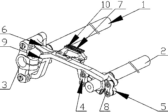
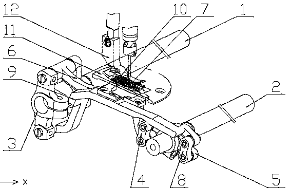
[0017] See figure 1 , A cloth feeding mechanism for a sewing machine, comprising a cloth feeding shaft 1, a tooth lifting shaft 2, a cloth feeding crank 3, a first bracket 6, a second bracket 9, a first feeding dog 7 and a second feeding dog 10 The cloth feed crank 3 includes a vertical double-head drive end symmetrically arranged at 180°, and is characterized in that it also includes a tooth-raising crank 5, and the cloth feed shaft 1 and the cloth feed crank 3 connected to it are located In the front part of the cloth direction, the thread lifting shaft 2 is a swing shaft and located at the rear part of the cloth feeding direction, and the thread lifting crank 5 is a double crank structure arranged at 180° in the cloth feeding direction (located in the cloth feeding direction). Rear part), the middle part is connected with the tooth lifting shaft 2, the end of the first tooth frame ...


PUM


Abstract

The invention relates to the technical field of mechanisms of sewing machines, in particular to a cloth feed mechanism of a sewing machine. The cloth feed mechanism of the sewing machine aims to solve the problems that potential safety hazard exists, cost is high and working efficiency is low in the prior art. The cloth feed mechanism for the sewing machine comprises a cloth feed shaft, a feed lifting rock shaft, a cloth feed crank, a feed frame, a second frame, a first cloth feed dog and a second cloth feed dog, wherein the cloth feed crank is provided with double-end drive ends which are perpendicularly and symmetrically arranged by 180 degrees. The cloth feed mechanism of the sewing machine is characterized by further comprising a feed lifting rock shaft crank, the cloth feed shaft and the cloth feed crank connected with the cloth feed shaft are located at the front portion in the cloth feed direction, the feed lifting rock shaft is a swinging shaft and located at the rear portion in the cloth feed direction, the feed lifting rock shaft crank is of a double-crank structure arranged in the cloth feed direction by 180 degrees, the middle of the feed lifting rock shaft crank is connected with the feed lifting rock shaft, the end of the first feed frame is connected with the crank structure at the front portion through a first feed lifting connection rod, and the end of the second feed frame is connected with the crank structure at the rear portion through a second feed lifting connection rod.

Description

Technical field [0001] The invention relates to the technical field of sewing machine mechanisms, in particular to a cloth feeding mechanism for sewing machines. Background technique [0002] In the patent No. "2012200223171", a continuous cloth feeding mechanism for a sewing machine is disclosed. The continuous cloth feeding mechanism includes a cloth feeding shaft, a lifting shaft, a cloth feeding crank, a first bracket, a second bracket, The first feeding dog, the second feeding dog, the first raising link, the second raising link and the raising cam. The lifting cam is a double cam structure arranged symmetrically at 180°, a first lifting link and a second lifting link are arranged on the lifting cam, and the cloth feeding crank includes a vertical 180° symmetrical arrangement The double-headed driving end; the first tooth frame is arranged between one driving end of the cloth feeding crank and the action end of the first lifting link, the second tooth frame is arranged betw...

Claims


Application Information

Patent Timeline
IPC IPC(8): D05B27/02D05B27/24
Inventor 齐军畅卓丽红刘永
Owner XIAN TYPICAL IND
Why Eureka
Try Eureka