Cub feeding device for industrial breeding in animal husbandry

A technology of animal husbandry and cubs, applied in the field of animal husbandry, can solve problems such as easy to grab food, achieve the effect of improving protection, facilitating absorption, and improving feeding quality

Inactive Publication Date: 2020-08-04
胡锦强
View PDF18 Cites 4 Cited by
  • Summary
  • Abstract
  • Description
  • Claims
  • Application Information

AI Technical Summary

Problems solved by technology

[0004] Based on the technical problem that the existing cub feeding device tends to snatch food during the feeding process, the present invention proposes a cub feeding device for industrialized breeding of animal husbandry

Method used


Image

  • Cub feeding device for industrial breeding in animal husbandry
  • Cub feeding device for industrial breeding in animal husbandry
  • Cub feeding device for industrial breeding in animal husbandry

Examples


Embodiment 1

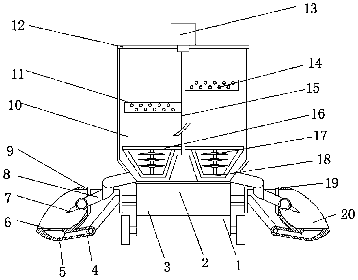
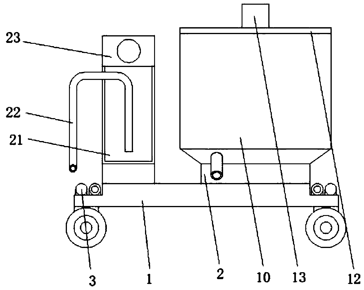
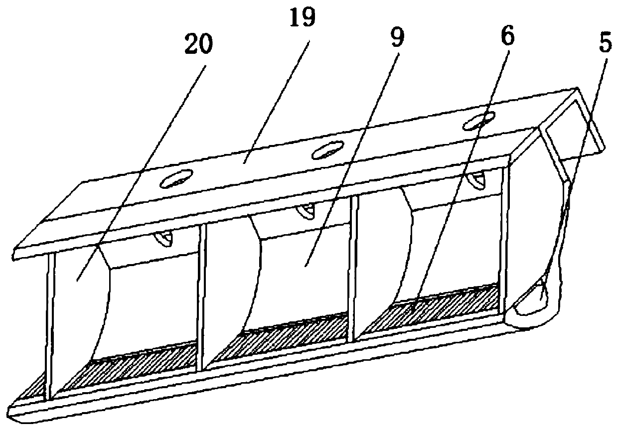
[0027] refer to Figure 1-4 , a cub feeding device for industrialized breeding of animal husbandry, comprising a vehicle seat 1, two support frames 2 are fixedly installed on the top of the vehicle seat 1, and a milk tank 10 and a residual liquid are fixedly installed on the top of the two support frames 2 respectively Tank 21, the top of the milk tank 10 is equipped with a cover 12 through a hasp lock and hinge, and the top of the cover 12 is fixedly installed with a driving motor 13, and both sides of the top of the car seat 1 are fixedly installed with two staggered electric motors. A push rod 3, and a connecting frame 19 is fixedly installed between the ends of two electric push rods 3 on the same side, a feeding trough 9 is fixedly installed on the outside of the connecting frame 19, and a plurality of isolation plates are arranged in the middle of the feeding trough 9 20. A feeding tube 8 with an L-shaped structure is fixedly installed between the side of the feeding tan...

Embodiment 2

[0035] refer to Figure 1-5 , a cub feeding device for animal husbandry industrialized breeding. Compared with Embodiment 1, the bottom of the stirring rod 16 is fixedly equipped with an extension rod 18 of U-shaped structure, and the extension rod 18 and the stirring rod 16 are fixed A shearing mechanism 17 is installed;

[0036] The shearing mechanism 17 includes a rod body and a plurality of shearing discs sleeved on the outside of the rod body, and the outer side of the shearing discs is provided with a ring-shaped cutting edge.

[0037] In this embodiment: when the drive motor 13 rotates in the device, the extension rod 18 and the shearing mechanism 17 at the bottom can stir and mix the milk at the bottom, and the multiple shearing blades on the shearing mechanism 17 can The undissolved milk powder mass in the milk is sheared and broken to improve the dissolution quality of the milk, which is more conducive to the absorption of the cubs.


PUM


Abstract

The invention belongs to the technical field of animal husbandry, particularly relates to a cub feeding device for industrial breeding in the animal husbandry, and aims to solve the problem that an existing cub feeding device is prone to cause food snatching in a feeding process. According to the scheme, the cub feeding device comprises a saddle; two supporting frames are fixedly mounted at the top of the saddle; a milk tank and a residual liquid tank are fixedly mounted at the top ends of the two supporting frames correspondingly; a sealing cover is mounted at the top end of the milk tank through a hasp lock and a hinge; and a driving motor is fixedly mounted at the top end of the sealing cover. When cubs are fed, feeding troughs are pushed out into a breeding fence through electric pushrods installed on the side surfaces, so that the cubs can be attached into the feeding trough for eating; the feeding troughs are separated through separation plates, so that the cubs are prevented from snatching for food, and the feeding quality is improved; and meanwhile, the flexible feeding troughs and the separation plates can prevent skin scratches of the cubs during eating and moving, so that the protection effect on the cubs is improved.

Description

technical field [0001] The invention relates to the technical field of animal husbandry, in particular to a cub feeding device for industrialized breeding of animal husbandry. Background technique [0002] Sheep is one of the domestic animals of human beings and is the main source of wool. The whole body of sheep is a treasure, and its fur can be made into various woolen and leather products. In terms of health care, sheep can play its unique role. Mutton, sheep blood, sheep bones, sheep liver, milk, sheep gallbladder, etc. can be used for the treatment of various diseases and have high medicinal value. Industrial sheep raising can effectively combine technology with management, and local resources can Being fully utilized, the potential of labor force and equipment conditions can be better utilized, and finally the scale effect can be maximized. [0003] In the process of industrialized sheep raising, sheep cubs will be raised alone for a period of time before being trans...

Claims


Application Information

Patent Timeline
Patent Type & Authority Applications(China)
IPC IPC(8): A01K9/00B01F13/10B01F1/00
CPCA01K9/00A01K9/005B01F21/10B01F33/8305B01F2101/18
Inventor 胡锦强
Owner 胡锦强
Why Eureka
Try Eureka