Pitched roof mounting system for solar thermal collector and construction method of pitched roof mounting system

A technology for solar collectors and installation systems, applied in solar thermal devices, solar thermal power generation, roofing, etc., can solve problems such as unstable installation of solar collectors, complicated installation and construction process, and unsightly installation effects, etc. Achieve perfect and convenient application, low aesthetics, and improve the effect of aesthetics

Active Publication Date: 2014-04-09
LJLZ BEIJING BUILDING MATERIALS CO LTD
View PDF10 Cites 1 Cited by
  • Summary
  • Abstract
  • Description
  • Claims
  • Application Information

AI Technical Summary

Problems solved by technology

[0003] The purpose of the present invention is to provide a sloping roof installation system for solar collectors and its construction method, to solve the traditional solar collector installation is not firm and unstable, easy to leak, complicated installation and construction process, and the installation effect is not beautiful technical problem

Method used


Image

  • Pitched roof mounting system for solar thermal collector and construction method of pitched roof mounting system
  • Pitched roof mounting system for solar thermal collector and construction method of pitched roof mounting system
  • Pitched roof mounting system for solar thermal collector and construction method of pitched roof mounting system

Examples


Embodiment Construction

[0050] Examples see Figure 1-10 As shown, the sloping roof installation system of this solar collector includes a sloping roof and a solar collector 12 installed on the sloping roof.

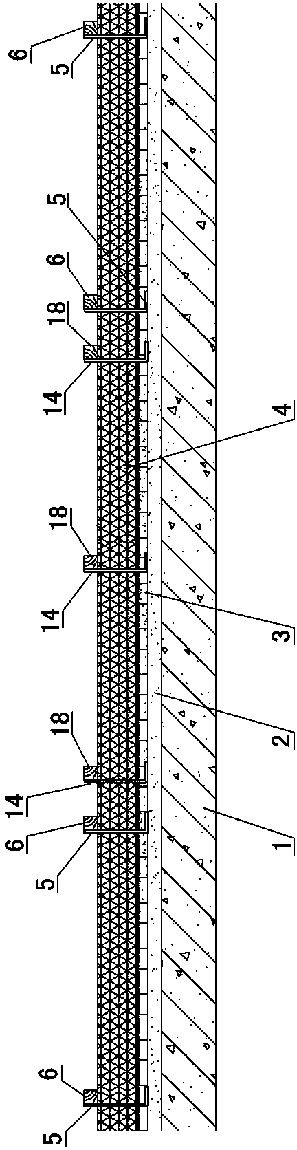
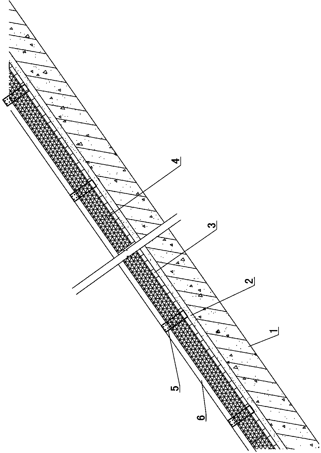
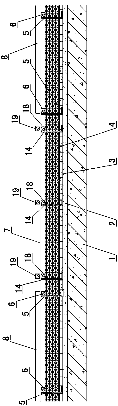
[0051] see Figure 9 , Figure 10 , the sloping roof consists of a structural layer 1, a cement mortar leveling layer 2 laid on the structural layer 1, a waterproof cushion layer 3 laid on the cement mortar leveling layer 2, a thermal insulation and drainage layer laid on the waterproof cushion layer 3, laying The horizontal tile-hanging wooden strip 8 on the insulation and drainage layer and the roof tile 9 hung on the horizontal tile-hanging wooden strip 8 are formed.

[0052] The thermal insulation and drainage layer is composed of thermal insulation board 4, backing bracket-5, longitudinally flowing wooden strips 6 and aluminum foil coiled material 7, and the backing bracket-5 is arranged on the waterproof cushion layer 3, and backing bracket-5 passes through The nails are fixedly connec...


PUM


Abstract

The invention discloses a pitched roof mounting system for a solar thermal collector and a construction method of the pitched roof mounting system. The system comprises a pitched roof and the solar thermal collector arranged on the pitched roof, wherein the pitched roof consists of a structural layer, a cement mortar leveling layer, a waterproof pad layer, a heat preservation water drainage layer, transverse tile hanging wood bars and roof tiles, wherein the heat preservation water drainage layer consists of a heat preservation plate, wood carrying brackets I, longitudinal downstream wood bars and an aluminum foil coiled material; two-side concave-shaped water drainage ditches are formed between the solar thermal collector and the longitudinal downstream wood bars on the left side and the right side of the solar thermal collector; an upper-side concave-shaped water drainage ditch is formed between the solar thermal collector and transverse lap-joint wood bars; a lower-side concave-shaped water drainage ditch is formed between the solar thermal collector and the roof tiles on the lower side of the solar thermal collector. According to the system and the construction method which are disclosed by the invention, the construction technology is changed; the solar thermal collector can be firmly and stably mounted; the pitched roof has energy-saving and ventilating effects; the heat insulation and preservation efficiency of the pitched roof can be improved, and the surface of a building is attractive.

Description

technical field [0001] The invention relates to a solar heat collector installation system arranged on a sloping roof, and a construction method of the solar heat collector installation system. Background technique [0002] Solar collectors are now widely used in daily life, especially in rural self-built houses and low-rise garden houses. Its disadvantages are: 1. The requirements for the outer surface of the building are relatively strict, and it is only suitable for low-end cement mortar paving. tile roof, and the installation is not firm and unstable, it is easy to leak, and the installation and construction process is complicated; 2. It cannot form a whole with the roof, which will easily affect the overall aesthetic feeling of the building. Contents of the invention [0003] The purpose of the present invention is to provide a sloping roof installation system for solar collectors and its construction method, to solve the traditional solar collector installation is no...

Claims


Application Information

Patent Timeline
Patent Type & Authority Applications(China)
IPC IPC(8): E04D11/02E04D13/16E04D13/064F24J2/46
CPCY02B10/20Y02E10/40
Inventor 郑秋锁
Owner LJLZ BEIJING BUILDING MATERIALS CO LTD
Why Eureka
Try Eureka