Unlock instant, AI-driven research and patent intelligence for your innovation.

Piston control type variable displacement vane pump

A variable displacement vane pump, control technology, applied in the direction of rotary piston pump, rotary piston machine, pump control, etc., can solve the problems of large volume and weight, increased processing cost, large space requirements, etc., to achieve overall response Good performance, reduced processing cost, small volume and weight

Inactive Publication Date: 2014-04-09
王光明
View PDF6 Cites 6 Cited by
  • Summary
  • Abstract
  • Description
  • Claims
  • Application Information

AI Technical Summary

Problems solved by technology

[0010] 1. Since the periphery of the control ring needs to be fed with high-pressure oil to control the control ring, the processing requirements of the shell are high, and the outside of the shell needs a large sealing surface, which increases the processing cost and requires a large space, resulting in volume and heavy
[0011]2. Due to structural limitations, the pre-tightening force of the spring is relatively large, resulting in a large space requirement for the spring, and the overall responsiveness of the pump becomes poor
[0012]3. Since the interior needs to be sealed, non-metallic parts need to be used for sealing, the reliability becomes poor, and the cost is high
[0013]4. It is impossible to make the displacement of the pump increase in the oil pressure state, but it can only work in the direction of reducing the displacement
[0014]5. All designs of the current structure need to pass high pressure to the outside of the control ring, resulting in complex shape and deformation of the control ring, which affects its performance
[0015]6. It is difficult to adjust the length of high and low pressure moments
[0016]7. Greatly affected by cavitation
[0017] 8. The control loop cannot achieve precise control

Method used


Image

  • Piston control type variable displacement vane pump
  • Piston control type variable displacement vane pump
  • Piston control type variable displacement vane pump

Examples


no. 1 example

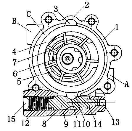
[0093] figure 1 It is a sectional view of the piston-controlled variable displacement vane pump according to the first embodiment of the present invention. Such as figure 1 As shown, the piston-controlled variable displacement vane pump of the present invention, wherein the pump housing 1 includes a pump chamber with an inlet A and an outlet B. The pump control ring 4 moves in the pump chamber to adjust the capacity of the vane pump. The vane pump rotor 5 is rotatably arranged in the pump control ring 4 , and the rotation axis of the vane pump rotor 5 deviates from the center of the pump control ring 4 . The vane ring 6 is rotatably arranged in the vane pump rotor 5 , and the vane ring 6 rotates around the center of the vane pump rotor 5 . Several vanes 7 are slidably passing through the vane pump rotor 5 respectively. The inner ends of the vanes 7 abut against the outer surface of the vane ring 6, and the outer ends abut against the inner surface of the pump control ring 4...

no. 2 example

[0106] image 3 It is a sectional view of a piston-controlled variable-displacement vane pump according to the second embodiment of the present invention. Such as image 3 As shown, the piston-controlled variable displacement vane pump of the present invention, wherein the pump casing 1 includes a pump chamber with an inlet A and an outlet B. The pump control ring 4 moves in the pump chamber to adjust the capacity of the vane pump. The vane pump rotor 5 is rotatably arranged in the pump control ring 4 , and the rotation axis of the vane pump rotor 5 deviates from the center of the pump control ring 4 . The vane ring 6 is rotatably arranged in the vane pump rotor 5 , and the vane ring 6 rotates around the center of the vane pump rotor 5 . Several vanes 7 are slidably passing through the vane pump rotor 5 respectively. The inner ends of the vanes 7 abut against the outer surface of the vane ring 6, and the outer ends abut against the inner surface of the pump control ring 4. ...

no. 3 example

[0117] Figure 5 It is a sectional view of the piston-controlled variable displacement vane pump according to the third embodiment of the present invention. Such as Figure 5 As shown, the piston-controlled variable displacement vane pump of the present invention, wherein the pump housing 1 includes a pump chamber with an inlet A and an outlet B. The pump control ring 4 moves in the pump chamber to adjust the capacity of the vane pump. The vane pump rotor 5 is rotatably arranged in the pump control ring 4 , and the rotation axis of the vane pump rotor 5 deviates from the center of the pump control ring 4 . The vane ring 6 is rotatably arranged in the vane pump rotor 5 , and the vane ring 6 rotates around the center of the vane pump rotor 5 . Several vanes 7 are slidably passing through the vane pump rotor 5 respectively. The inner ends of the vanes 7 abut against the outer surface of the vane ring 6, and the outer ends abut against the inner surface of the pump control ring...


PUM


Abstract

The invention discloses a piston control type variable displacement vane pump which comprises a pump shell, a pump control ring, a vane pump rotor, a vane ring, a plurality of vanes, an oil cylinder, a pump cover and a control piston, wherein the intermediate part of the oil cylinder is communicated with a pump chamber; the control piston is positioned at the intermediate part of the oil cylinder; the outer surface of the pump control ring is respectively provided with a first bulge and a second bulge, the first bulge is positioned in a first slide block positioning hole in the intermediate part of the control piston, and the second bulge is positioned in a second slide block positioning hole in the inner surface of the pump shell; the pump control ring is linked with the control piston and swing by taking the second slide block positioning hole as a basic point to change the volume capacity of the vane pump; a first cavity and a first control cavity are formed between both ends of the control piston and the inner wall of the oil cylinder respectively, the first cavity is internally provided with a reset spring, the first control cavity is sealed with the pump chamber, a pressurized fluid is introduced into the first control cavity to generate force to move the pump control ring so as to reduce the volume capacity of the vane pump, and the reset spring resists the force inside the first control cavity to establish equilibrium.

Description

technical field [0001] The invention relates to the field of variable-displacement vane pumps, and more specifically, to a piston-controlled variable-displacement vane pump. Background technique [0002] The inner surface of the stator of the variable vane pump is a circle, and there is an eccentric distance between the rotor and the stator. There is only one oil suction window and one oil pressure window on the oil distribution plate. When the rotor is driven by the motor and rotates in the direction of the arrow in the figure, when the blade passes through the lower half of the stator, under the action of centrifugal force, it protrudes from the blade groove, and the sealing volume between the two blades increases to realize oil absorption; the blade passes through the stator In the upper half, it is gradually pressed into the vane groove by the inner surface of the stator, and the sealing volume is reduced to realize oil pressure. Every time the rotor of the pump rotate...

Claims


Application Information

Patent Timeline
IPC IPC(8): F04C2/344F04C14/22
Inventor 王光明秦翔宇荀生平
Owner 王光明