Integrated hydraulic oil testing system

A technology of comprehensive testing and hydraulic oil, applied in the field of testing, can solve the problems of increased internal leakage, economic losses, and reduced system response speed, so as to reduce failures and improve production life.

Inactive Publication Date: 2014-04-09
CHENGDU RUIBO INVESTMENT
View PDF5 Cites 12 Cited by
  • Summary
  • Abstract
  • Description
  • Claims
  • Application Information

AI Technical Summary

Problems solved by technology

The pollution sources of hydraulic oil are mainly divided into solid particles, water and air. Solid particles will accelerate the wear of hydraulic components, increase internal leakage, and seriously block the movement of components. The entry of water can reduce the lubricating performance of hydraulic oil and accelerate Oxidative deterioration, cavitation, air mixed into the hydraulic oil can cause the oil temperature to rise, the system working pressure to decrease, and the system response speed to decrease. The hydraulic oil pollution will cause damage to the hydraulic components, causing hydraulic oil system failure, and affecting the safety and stability of the wheel. , but also caused economic losses to users
[0003] At present, in the control of hydraulic oil pollution in the hydraulic system, the hydraulic system is mostly equipped with a filter to control the solid particle pollution of the hydraulic oil. Although this method can filter the hydraulic oil to a certain extent and reduce the pollution of the hydraulic oil, there is a problem. The biggest defect is that there is no specific basis for when the filter needs to be replaced, and there is no predictive analysis of the hydraulic oil pollution situation

Method used


Image

  • Integrated hydraulic oil testing system

Examples


Embodiment Construction

[0014] The present invention will be further described below in conjunction with accompanying drawing:

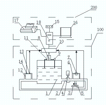
[0015] Such as figure 1 As shown, the present invention includes a data acquisition device 100 and a monitoring device 200, and the data acquisition device 100 includes a sampling oil tank 1, an oil delivery pump 4, a turbidity detector 7, an oil pressure detector 5, a viscosity detector 8, and micro-water detection device 13, oil temperature detector 14 and acquisition data converter 10, the outlet of the circuit oil pipe 2 of the sampling oil tank 1 is provided with an oil delivery pump 4, and the outlet end of the oil delivery pump 4 is provided with a first oil pipe branch 6 and a second Two oil pipe branches 12, the first oil pipe branch 6 is provided with a turbidity detector 7, the second oil pipe branch 12 is provided with a micro water detector 13 and an oil temperature detector 14, and the oil pressure detector 5 is arranged in the circuit On the oil pipe 2, a sa...


PUM


Abstract

The invention discloses an integrated hydraulic oil testing system. The integrated hydraulic oil testing system comprises a data acquisition device and a monitoring device, wherein the data acquisition device comprises a sampling oil tank, an oil circuit conveying pump, a turbidity detector, an oil pressure detector, a viscosity detector, a brackish water detector, an oil temperature detector and an acquired data converter. By using the integrated hydraulic oil testing system, the turbidity, the viscosity and the moisture of hydraulic oil can be detected in an online manner; a worker can timely find out change of the hydraulic oil and then takes corresponding measures, the possibility of faults of equipment is reduced, and the service life of the equipment is prolonged.

Description

technical field [0001] The invention relates to the technical field of testing, in particular to a hydraulic oil comprehensive testing system. Background technique [0002] According to statistics, 80% of hydraulic system failures are caused by hydraulic oil pollution. The pollution sources of hydraulic oil are mainly divided into solid particles, water and air. Solid particles will accelerate the wear of hydraulic components, increase internal leakage, and seriously block the movement of components. The entry of water can reduce the lubricating performance of hydraulic oil and accelerate Oxidative deterioration, cavitation, air mixed into the hydraulic oil can cause the oil temperature to rise, the system working pressure to decrease, and the system response speed to decrease. The hydraulic oil pollution will cause damage to the hydraulic components, causing hydraulic oil system failure, and affecting the safety and stability of the wheel. , but also caused economic losse...

Claims


Application Information

Patent Timeline
Patent Type & Authority Applications(China)
IPC IPC(8): F15B19/00
Inventor 龚攀
Owner CHENGDU RUIBO INVESTMENT
Why Eureka
Try Eureka