
Power tower bottom gate valve

A gate valve, electric technology, used in sliding valves, valve details, valve devices and other directions, can solve the installation and maintenance conditions of rectangular gate valves that do not have hydraulic drive, and can not fully meet the full range of installation, installation and maintenance. The problem of large occupation space, etc., achieves the effect of improving equipment site safety, small occupation space, and easy maintenance and replacement.

Inactive Publication Date: 2014-04-09
XIANGYANG HANGSHENG PETRO CHEM ENVIRONMENTAL PROTECTION EQUIP
View PDF6 Cites 3 Cited by
  • Summary
  • Abstract
  • Description
  • Claims
  • Application Information

AI Technical Summary

Problems solved by technology

The failure rate of the hydraulic system of the hydraulically driven rectangular gate valve and sector valve is relatively high, and the operation of the tower bottom valve cannot be performed when the hydraulic system fails or the tower bottom is powered off
Hydraulically driven rectangular gate valves occupy too much space for installation and maintenance, and the space at the bottom of most old coke towers does not have the conditions for installation and maintenance of hydraulically driven rectangular gate valves; although hydraulically driven sector valves occupy space for installation and maintenance The space is smaller than the hydraulically driven rectangular gate valve, but it still cannot fully meet the conditions for all-round installation of the bottom space of most old coke towers

Method used


Image

  • Power tower bottom gate valve
  • Power tower bottom gate valve
  • Power tower bottom gate valve

Examples


Embodiment Construction

[0039] Preferred embodiments of the present invention are described below, and it should be understood that the preferred embodiments described here are only used to illustrate and explain the present invention, and are not intended to limit the present invention.

[0040] as attached figure 1 to attach Figure 8 shown.

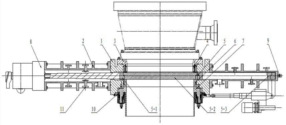
[0041] The valve adopts all-electric operation, without hydraulic system; electric, pneumatic and manual valve opening and closing operations can be performed; the occupied space is small, which can meet the conditions for all-round installation and maintenance of the coke tower bottom space; remote control can be realized.

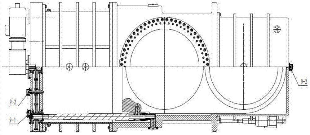
[0042] Such as figure 2 and 3As shown, the electric valve has a housing 1, the upper and lower ends of the housing 1 are respectively provided with through holes, an upper flange, and a lower flange, and the upper flange of the housing 1 is connected to the lower port of the upstream channel through the sealing seat 3. The through h...


PUM


Abstract

The invention relates to a power tower bottom gate valve consisting of a valve body, end sockets, a sealing component, a gate component, an electric gate component driving mechanism and an electric mechanism that is used for applying external sealing force. Through holes, an upper and a lower flanges are respectively arranged on the upper end face and the lower end face of a casing of the valve body, the valve body and the end sockets are connected to from a closed cavity, and the gate component is capable of moving inside the closed cavity. The sealing component comprising a sealing seat, an upper sealing ring and a lower sealing ring realizes sealing of the components, in relative movements, of the gate valve. The electric gate component driving mechanism drives the gate component to move through a motor that serves as a power source. Through a motor serving as a power source, the electric mechanism for applying external sealing force acts on the sealing rings to provide sealing force. The power tower bottom gate valve without hydraulic systems is operated automatically fully, capable of meeting requirements of all-round installation conditions in bottom spaces of all types of coking drums due to its small space occupation, further, is high in safety and good in running environment, and capable of being on and off electrically, pneumatically and manually and controlled remotely.

Description

technical field [0001] The invention belongs to the technical field of delayed coking devices in the petrochemical industry, and specifically relates to an electric gate valve, in particular to an electric tower bottom gate valve for a coke tower used for opening and closing the bottom of a coke tower. Background technique [0002] At present, most coke tower bottom devices in the domestic petrochemical industry use flange-type bottom cover machines. Flange-type bottom cover machines occupy a large space, have low automation, low work efficiency, low safety, and poor working environment. In recent years, some coke tower bottom devices have adopted hydraulically driven rectangular gate valves and hydraulically driven sector valves. The failure rate of the hydraulic system of the hydraulically driven rectangular gate valve and sector valve is relatively high, and the operation of the tower bottom valve cannot be performed when the hydraulic system fails or the tower bottom is ...

Claims


Application Information

Patent Timeline
IPC IPC(8): F16K3/16F16K3/314F16K31/04F16K31/50F16K37/00F16K51/00
CPCF16K3/0281F16K3/18F16K3/314F16K31/047F16K31/508F16K31/54F16K37/0041F16K51/00
Inventor 林达镛汪蓬毛辉朱爱青陈保申
Owner XIANGYANG HANGSHENG PETRO CHEM ENVIRONMENTAL PROTECTION EQUIP
Learn More