Microchannel flat tube wound heat exchanger with variable hydraulic diameter in the same flow path

A hydraulic diameter, micro-channel technology, applied in heat exchanger types, indirect heat exchangers, lighting and heating equipment, etc., can solve the problems of pressure drop in the inlet section, deviation of heat transfer performance in the outlet section, etc. The effect of pressure resistance, reducing flow resistance, and enhancing heat transfer effect

Active Publication Date: 2015-12-16
CHINA NAT OFFSHORE OIL CORP +1
View PDF6 Cites 0 Cited by
  • Summary
  • Abstract
  • Description
  • Claims
  • Application Information

AI Technical Summary

Problems solved by technology

[0003] The Chinese patent application number is 200680027902.8, and the application titled "Wound Heat Exchanger with Different Pipe Diameters" improves the existing wound heat exchanger. The wound heat exchanger of this invention is only in different flow paths. The use of circular tubes with different diameters is beneficial to take into account the differences in the characteristics of heat transfer media in different flow paths, but it does not solve the problem of large pressure drop at the inlet section and deviation of heat transfer performance at the outlet section in the same flow path

Method used


Image

  • Microchannel flat tube wound heat exchanger with variable hydraulic diameter in the same flow path
  • Microchannel flat tube wound heat exchanger with variable hydraulic diameter in the same flow path

Examples


Embodiment Construction

[0021] The present invention will be further described below in conjunction with the accompanying drawings, but the present invention is not limited to the following embodiments.

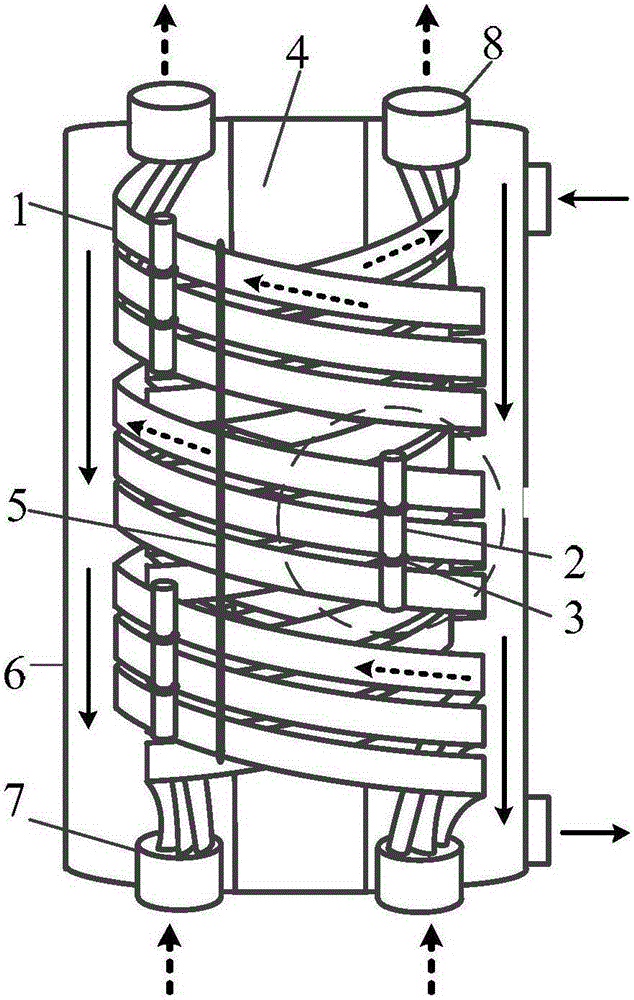
[0022] Such as figure 1 and figure 2 As shown, the microchannel flat tube winding heat exchanger with variable hydraulic diameter in the same flow path provided by the present invention includes a heat exchanger body; the housing 6 of the heat exchanger body is provided with three microchannel flat tubes 1 The three micro-channel flat tubes 1 are coiled around the central tube 4 in the shell 6 as the center. Openings at both ends of the microchannel flat tube 1 are respectively connected with an inlet tube 7 at the bottom of the housing 6 and an outlet tube 8 at the top of the housing 6 .

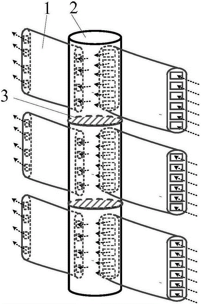
[0023] Such as figure 2 As shown, the cavity of each microchannel flat tube 3 is provided with multiple microchannel flow paths (not marked in the figure). The three micro-channel flat tubes of each layer o...


PUM


Abstract

The invention discloses a micro-channel flat tube wound heat exchanger with the variable hydraulic diameter in a same flow path. The micro-channel flat tube wound heat exchanger comprises a heat exchanger body; a plurality of micro-channel flat tubes are arranged in a shell of the heat exchanger body, and the micro-channel flat tubes are circled in a wound mode with a center cylinder arranged in the shell as the center; the openings in the two ends of each micro-channel flat tube are connected with an inlet pipe arranged at the bottom of the shell and an outlet pipe arranged at the top of the shell respectively; a plurality of micro-channel flow paths are arranged in a cavity of each micro-channel flat tube; each micro-channel flat tube in each micro-channel flat tube layer is connected with at least one collecting tube which is a tube with the two ends closed; the micro-channel flow paths are communicated with the collecting tubes, and the numbers, the hole diameters and / or the shapes of the cross sections of the micro-channel flow paths arranged on the two sides of the collecting tubes are different. The hydraulic diameter of a tube through which fluid flows in the process of conversion from the gas phase to the liquid phase keeps decreasing, and not only is flow resistance of gas in a front gas tube segment reduced, but also the heat exchange effect of liquid in the following liquid tube segment is enhanced.

Description

technical field [0001] The invention relates to a microchannel flat tube winding heat exchanger with variable hydraulic diameter in the same flow path, which belongs to the equipment in the technical field of low temperature heat exchange. Background technique [0002] Wound tube heat exchangers are the primary cryogenic heat exchangers of choice for large onshore natural gas liquefaction plants. According to statistics, 90% of large-scale onshore natural gas liquefaction plants use coiled tube heat exchangers. The wound tube heat exchanger is formed by winding a plurality of circular tubes around a central tube layer by layer. The medium flowing in the circular tube exchanges heat with the medium flowing in the shell. The prior art (Hausen / Linde, Cryogenic Technology, 2nd Edition, 1985, pp. 471-475; Gu Anzhong, Liquefied Natural Gas Technical Handbook, 1st Edition, 2012, pp. 484-485) reported wound tube heat exchangers , but most of them use winding pipes of equal diamet...

Claims


Application Information

Patent Timeline
Patent Type & Authority Patents(China)
IPC IPC(8): F28D7/02
Inventor 陈杰浦晖花亦怀密晓光丁国良王婷婷
Owner CHINA NAT OFFSHORE OIL CORP
Why Eureka
Try Eureka