Method for manufacturing heliostats with mirror surfaces having different curvatures

A technology of heliostat and curvature, applied in installation, optics, instruments, etc., can solve the problem of inability to meet the design requirements of large-area heliostat mirror field, and achieve the effect of a wide range of applications

Active Publication Date: 2014-04-09
ZHEJIANG SUPCON SOLAR TECHNOLOGY CO LTD
View PDF7 Cites 2 Cited by
  • Summary
  • Abstract
  • Description
  • Claims
  • Application Information

AI Technical Summary

Problems solved by technology

Therefore, the design goal of the heliostat is: the profile of the light spot reflected to the heat sink is regular, the area is small, and the energy of the light spot is uniform. However, the current mirror design of the heliostat is carried out after the mirror surface is completed, which cannot meet the needs of large-area heliostats. Mirror Field Design Requirements

Method used


Image

  • Method for manufacturing heliostats with mirror surfaces having different curvatures
  • Method for manufacturing heliostats with mirror surfaces having different curvatures
  • Method for manufacturing heliostats with mirror surfaces having different curvatures

Examples


Embodiment 1

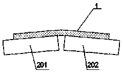
[0034] Embodiment one: if figure 1 As shown, in this embodiment, the curvature surface of the heliostat mirror surface of the mold platform is a curved surface of a specific radian formed by the combination of two surfaces 201 and 202, so that the mirror surface of the heliostat 1 is flattened with the mold platform of the group, and a specific surface is produced. arc surface.

Embodiment 2

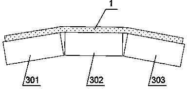
[0035] Embodiment two: if figure 2 As shown, the curvature surface of the heliostat mirror surface of the mold platform in this embodiment is composed of three surfaces 301, 302, and 303 combined to form a curved surface with a specific radian, so that the mirror surface of the heliostat 1 is flattened with the mold platform of this group , making a specific arc.

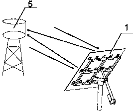
[0036] Such as image 3 As shown, after the single-sided heliostat 1 provided by Embodiment 1 and Embodiment 2 is flattened with the mold platform and successfully manufactured, the sun’s parallel light is converged to the heat absorber 5 to form a relatively concentrated light spot, thereby realizing mirror convergence. light effect.

Embodiment 3

[0037] Embodiment Three: In this embodiment, the heliostat includes a multi-faceted reflector, such as Figure 4 As shown, the heliostat 1 is composed of multi-faceted reflectors, for example, it may be composed of four-faced reflectors 101, 102, 103, 104 in this embodiment, but it is not limited thereto. In this embodiment, the curvature surface of the heliostat mirror surface of the mold platform is a curved surface with a specific radian formed by the combination of four surfaces 401, 402, 403, and 404, so that the mirror surfaces of the heliostats 101, 102, 103, and 104 are respectively in line with the set of molds. The four surfaces 401, 402, 403, 404 of the platform are flattened to form a specific arc.

[0038] Such as Figure 5 As shown, after the multi-faceted heliostat 1 in the third embodiment is flattened with the mold platform, the sun's parallel light is converged to the heat absorber 5 to form a relatively concentrated light spot, thereby achieving the effect ...


PUM


Abstract

The invention provides a method for manufacturing heliostats with mirror surfaces having different curvatures. According to the method, a die platform which can be used for freely adjusting the curvatures of the mirror surfaces of the heliostats are used, the curvatures of the mirror surfaces of the heliostat can be adjusted through the platform, and therefore the heliostats with the mirror surfaces having the different curvatures or with different reflection distances is manufactured. Meanwhile, when heliostat supports are manufactured, a plurality of installation grooves or holes for adjusting the installation position are added, bonding sheets on the mirror surfaces and the installation holes of the heliostat supports have adjusting space, and therefore the heliostats with the mirror surfaces having the different curvatures can be assembled by means of the same batch of heliostat supports, the same batch of mirror surfaces and the same bonding platform.

Description

technical field [0001] The invention relates to the field of tower solar power generation, in particular to a method for manufacturing different curvatures of heliostat mirror surfaces. Background technique [0002] As a clean and renewable energy, solar energy has been applied more and more, especially photothermal power generation technology is an emerging solar energy utilization technology after photovoltaic power generation technology. Among several photothermal power generation technologies, tower-type solar thermal power generation uses a large number of heliostats to gather sunlight to the heat absorber installed on the top of the heat-absorbing tower, heats the working medium, generates steam, and drives the steam turbine to drive the generator. generate electricity. Among them, the heliostat sun-chasing movement is one of the key technologies of tower-type solar thermal power generation. The entire heliostat field is composed of thousands of heliostats. The posit...

Claims


Application Information

Patent Timeline
Patent Type & Authority Applications(China)
IPC IPC(8): G02B7/183G02B7/198
Inventor 杨渊思张旭中黄文君徐能江远才钟国庆田军
Owner ZHEJIANG SUPCON SOLAR TECHNOLOGY CO LTD
Why Eureka
Try Eureka