Equipment for testing resistance to environmental stress of plastic

A technology that is resistant to environmental stress and testing equipment. It is applied in the direction of applying stable tension/pressure to test material strength, measuring devices, and analyzing materials. problem, to achieve ideal compression effect, easy processing and assembly, and low manufacturing cost

Inactive Publication Date: 2016-08-17
KINGFA SCI & TECH CO LTD +1
View PDF6 Cites 3 Cited by
  • Summary
  • Abstract
  • Description
  • Claims
  • Application Information

AI Technical Summary

Problems solved by technology

[0006] Patent CN103364262A discloses a combination device for polymer environmental stress cracking experiments, but its airtight effect is difficult to meet the requirements of the above-mentioned volatile solvents
The test equipment is complicated, and it is difficult to conduct high and low temperature cycle tests on materials in experiments, which is not very practical
In addition, the equipment has a lot of spare parts, high cost and low versatility

Method used


Image

  • Equipment for testing resistance to environmental stress of plastic
  • Equipment for testing resistance to environmental stress of plastic
  • Equipment for testing resistance to environmental stress of plastic

Examples


Embodiment 1

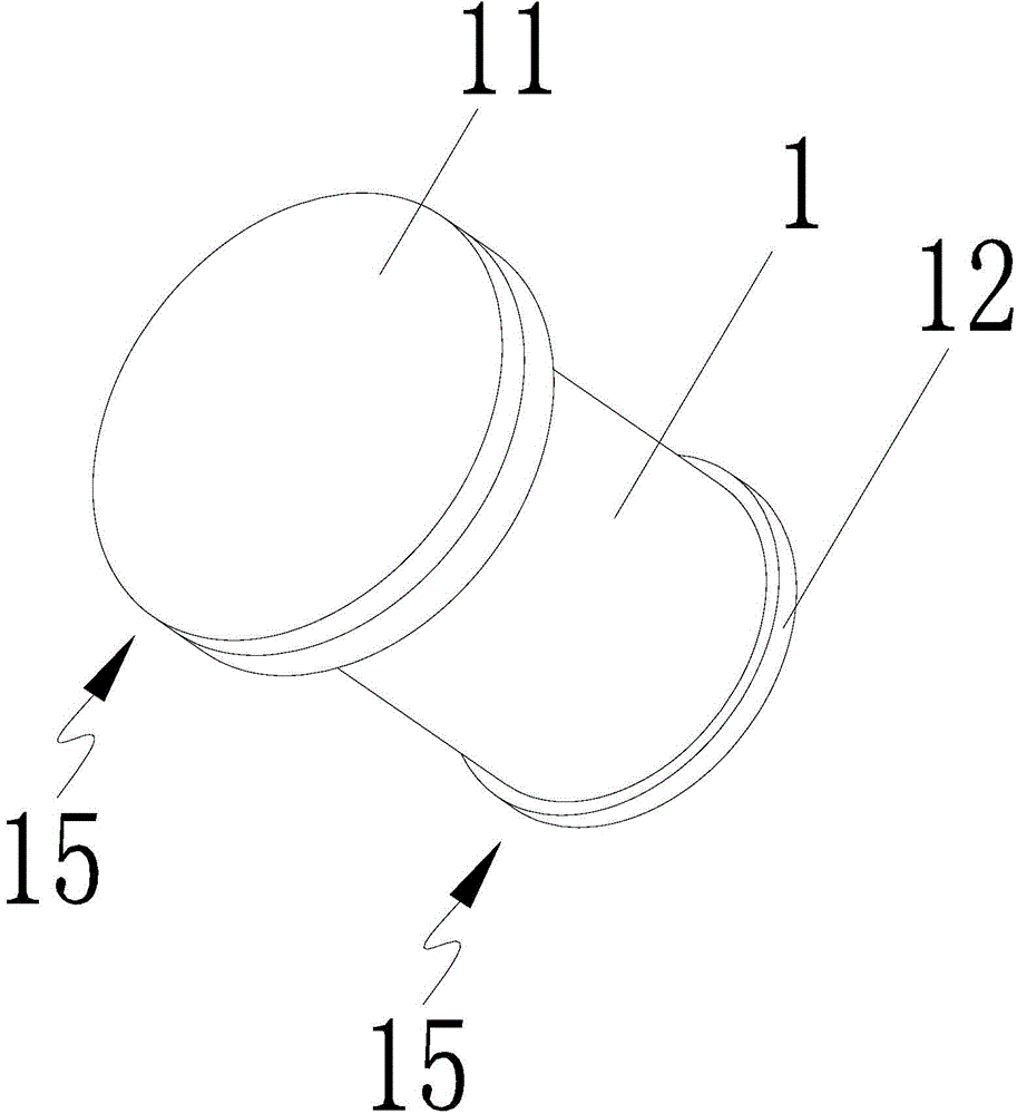
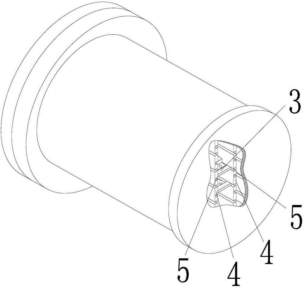
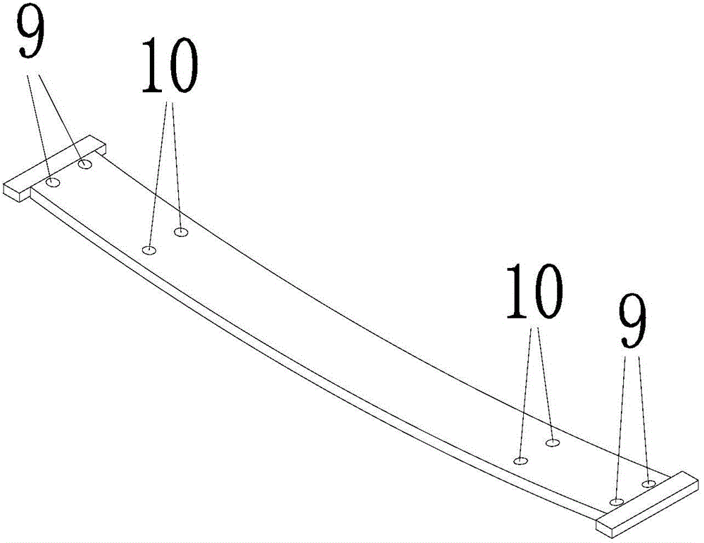
[0030] A plastic environmental stress testing device, comprising a test chamber 1, a frame bar 3 that bends a test sample 2, and a cover 15 that seals the test chamber 1, and the frame bar 3 is arranged in the test chamber 1 , preferably, a slot is provided in the test cavity 1, and the frame bar 3 is connected in the slot. The test cavity 1 is provided with at least two slot plates 4 , and the opposite sides of the two slot plates 4 are correspondingly provided with slots 5 , and the clamping slot is formed between the two slots 5 . Guide blocks 6 protrude from both ends of the frame bar 3 to both sides. The guide block 6 is connected in the draw-in groove, and can slide in the draw-in groove. By virtue of the cooperation of the guide block 6 and the draw-in groove, the frame bar 3 can be easily loaded and drawn out, which is convenient for testing.

[0031] Preferably, the curvature ε of the frame bar 3 is ε=d / (2r+d)×100%, wherein, r is the radius of the frame bar 3, and d ...

Embodiment 2

[0038] The difference between this embodiment and the first embodiment lies in that: the frame bar 3 is straight, and the frame bar 3 is shorter than the test sample bar 2 . In this way, after the two ends of the test sample 2 and the frame bar 3 are respectively fixed, the test sample 2 is bent due to the length difference between the frame bar 3 and the test sample 2, thereby meeting the requirements of the test. The curvature of the spline 2 is controlled by the length difference between the frame bar 3 and the test sample 2. The greater the length difference between the two, the greater the bending of the test sample 2, that is, the smaller the radius of the test sample 2, the greater the test sample 2. The greater the bending stress, on the contrary, the smaller the length difference between the two, the smaller the bending of the test sample 2, that is, the larger the radius of the test sample 2, the smaller the bending stress of the test sample 2, so it can meet differen...


PUM


Abstract

The present invention discloses equipment for testing resistance to environmental stress of plastic. The equipment includes a test chamber, a rack bar for bending the test strip and a cover for sealing the test chamber; the test chamber is internally provided with a neck; and the rack bar is connected in the neck. The present invention has high degree of tightness, and can conduct an environmental stress cracking test on a volatile test reagent; the equipment is made of stainless steel with certain thickness, has the advantages of ideal compression effect, overall safety and reliability, flexible handling, easiness to clean and operate; the rack bar has wide range of bending rate, meets test requirements of different materials; the test results are easy for comparison; and the equipment is easy for processing and assembly, and has low manufacturing cost.

Description

technical field [0001] The invention relates to the field of plastic testing equipment, in particular to a plastic environmental stress testing equipment. Background technique [0002] According to statistical analysis, 25% of plastic parts are damaged due to environmental stress cracking. Environmental stress cracking of plastics mainly refers to the process that polymer materials are prone to craze under specific stress and solvent environment, which eventually leads to cracking and failure. [0003] In some applications, plastics will definitely come into contact with environmental media, such as battery casings and refrigerator liner materials. In contact with the liner, the inner liner will partially soften, and then the stress will be locally relaxed and cracks will be generated, which will eventually lead to cracking and failure of the refrigerator inner liner, which brings a very high risk of accidents to refrigerator manufacturers and users. Therefore, the environ...

Claims


Application Information

Patent Timeline
Patent Type & Authority Applications(China)
IPC IPC(8): G01N3/08G01N17/00
Inventor 程庆蒋贤智何超雄陈平绪王林
Owner KINGFA SCI & TECH CO LTD
Why Eureka
Try Eureka