Charging network system applied to electric vehicle

A charging network and electric vehicle technology, applied in the direction of electric vehicle charging technology, electric vehicles, battery circuit devices, etc., can solve the problems of lack of systematic management of charging piles, achieve good charging guidance services, realize unattended, and improve experience Effect

Active Publication Date: 2014-04-09
上海ABB联桩新能源技术有限公司 +1
View PDF4 Cites 25 Cited by
  • Summary
  • Abstract
  • Description
  • Claims
  • Application Information

AI Technical Summary

Problems solved by technology

[0004] The purpose of the present invention is to provide a charging network system applied to electric vehicles to solve the problems of lack of effective systematic management of charging piles in the prior art

Method used


Image

  • Charging network system applied to electric vehicle
  • Charging network system applied to electric vehicle
  • Charging network system applied to electric vehicle

Examples


no. 1 example

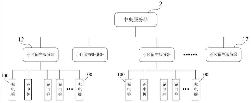
[0025] figure 1 It shows a schematic structural diagram of the charging network system applied to electric vehicles in the first embodiment of the present invention. Such as figure 1 As shown, the charging network system includes: a central server 2, and one or more multi-level regional charging networks establishing a communication connection with the central server 2. In the multi-level regional charging network, including The community guard server 12 connected by communication, and one or more charging piles 10 establishing a communication connection with the community guard server 12 .

[0026] Each charging pile 100 is distributed at each charging station in different communities. In this embodiment, the "community" here is understood in a broad sense, not only in the actual geographical radiation range (such as a coverage area with a radius of 3 kilometers, 5 kilometers or 10 kilometers), but also in the planning and definition of administrative or quasi-administrativ...

no. 2 example

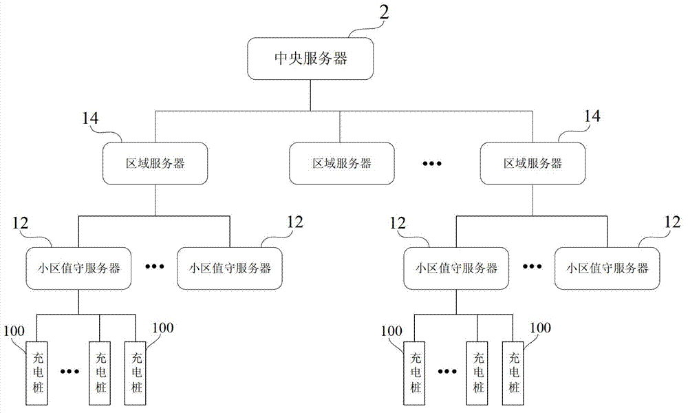
[0039] figure 2 It shows a schematic structural diagram of the charging network system applied to electric vehicles in the second embodiment of the present invention. In the second embodiment, the charging network system of the present invention includes a central server 2 and one or more multi-level regional charging networks establishing a communication connection with the central server 2 . Compared with the first embodiment, in the second embodiment, the multi-level regional charging network in the charging network system of the present invention adopts a two-level regional charging network. Specifically, as figure 2 As shown, in the second embodiment, the multi-stage regional charging network includes: one or more regional servers 14 governed by the central server 2, one or more community watch servers 12 governed by the regional server 14, and One or more charging piles 100 under the jurisdiction of the cell watch server 12 . Each charging pile 100 is distributed in...

no. 3 example

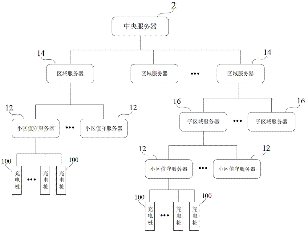
[0041] image 3 A schematic structural diagram of a charging network system applied to electric vehicles in a third embodiment of the present invention is shown. In the third embodiment, the charging network system of the present invention includes a central server 2 and one or more multi-level regional charging networks establishing a communication connection with the central server 2 . Compared with the first embodiment, in the third embodiment, the multi-level regional charging network in the charging network system of the present invention adopts a three-level regional charging network. Specifically, as image 3 As shown, in the third embodiment, the multi-level regional charging network includes: one or more regional servers 14 governed by the central server 2, one or more sub-regional servers 16 governed by the regional server 14 and / or the cell guard server 12 , one or more cell guard servers 12 governed by the sub-area server 16 , one or more charging piles 100 gove...


PUM


Abstract

The invention discloses a charging network system applied to an electric vehicle. The system comprises one or more multi-level region charging networks which are delimited based on geographic regions. Each multi-level region charging network comprises one or more charging piles distributed in the geographical region. Each charging pile is provided with a charging connecting unit which is connected with the electric vehicle. A central server which establishes communication connection with the multi-level region charging networks is used for comprehensively managing each multi-level region charging network, grasping and updating the running state of each charging pile under the jurisdiction of the multi-level region charging network in real time, and providing corresponding information service and / or operation control according to the running state. Compared with the prior art, the charging network system provided by the invention has the advantages that hierarchy type system networking management is carried out on scattered individual charging piles in a community management mode; unattended operation is realized; and unified management and control can be carried out on the charging piles.

Description

technical field [0001] The invention relates to the technical field of electric vehicles, in particular to a charging network system applied to electric vehicles. Background technique [0002] With the increasingly intensified contradictions between economic development, energy supply, and environmental pollution, energy conservation and consumption reduction and reduction of dependence on fossil fuels have become urgent problems to be solved for the sustainable economic development of countries all over the world. Electric vehicles have the advantages of fuel saving, environmental protection, and high efficiency. Scientists and industrial circles all over the world generally believe that electric vehicles are an important clean transportation tool in the 21st century. [0003] To achieve the popularization of electric vehicles, the first problem is to solve the charging problem of electric vehicles. Therefore, electric vehicle charging stations and charging networks are imp...

Claims


Application Information

Patent Timeline
Patent Type & Authority Applications(China)
IPC IPC(8): H02J7/00
CPCY02T90/168Y04S30/12Y02T90/167
Inventor 王华庚毛纯华毛纯清王培
Owner 上海ABB联桩新能源技术有限公司
Why Eureka
Try Eureka