Method for building wireless intersystem electromagnetic interference allowance calculation model

A radio system, electromagnetic interference technology, applied in transmission systems, electrical components, transmission monitoring, etc., can solve problems such as mutual interference

Active Publication Date: 2014-04-09
陕西海泰电子有限责任公司
View PDF3 Cites 8 Cited by
  • Summary
  • Abstract
  • Description
  • Claims
  • Application Information

AI Technical Summary

Problems solved by technology

[0003] In communication, between mobile communication base station equipment, when mobile communication base station equipment and microwave communication equipment are installed in the same station, mutual interference may occur

Method used


Image

  • Method for building wireless intersystem electromagnetic interference allowance calculation model
  • Method for building wireless intersystem electromagnetic interference allowance calculation model
  • Method for building wireless intersystem electromagnetic interference allowance calculation model

Examples


Embodiment Construction

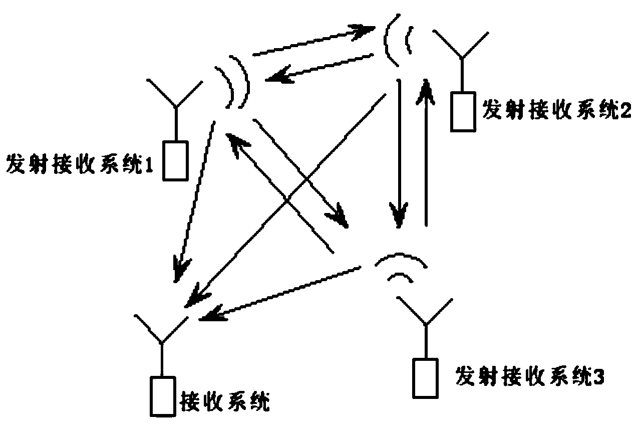
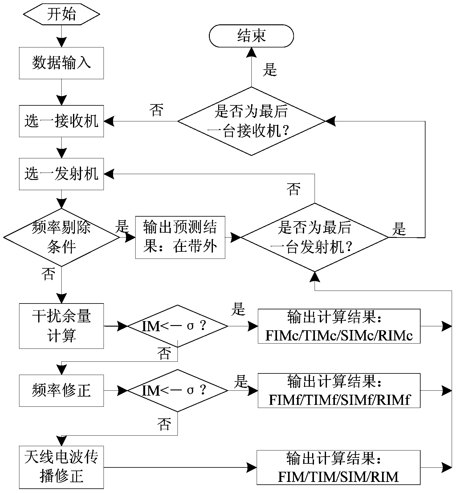
[0126] Based on the parametric model of transmitter, receiver, antenna and radio wave propagation, the present invention establishes fundamental wave interference margin (FIM), transmitter interference margin (TIM), receiver interference margin (RIM), clutter interference margin Four typical inter-system electromagnetic interference margin calculation models (SIM), the four typical inter-system interference margins are defined as follows:

[0127] Fundamental Interference Margin (FIM)—transmitter fundamental emission and receiver fundamental response;

[0128] Transmitter Interference Margin (TIM) - Transmitter fundamental emission and receiver clutter response;

[0129] Receiver Interference Margin (RIM) - transmitter clutter emission and receiver fundamental response;

[0130] Clutter Interference Margin (SIM) - Transmitter clutter emission and receiver clutter response.

[0131] At the same time, the present invention proposes a correction method for the electromagnetic i...


PUM


Abstract

The invention relates to a method for building a wireless intersystem electromagnetic interference allowance calculation model. The method for building the wireless intersystem electromagnetic interference allowance calculation model comprises the following steps that firstly, a wireless system which comprises a transmitter and a receiver is selected; secondly, whether the wireless system in the first step meets the condition of frequency elimination or not is judged, wherein if yes, the electromagnetic interference allowance calculation process is not executed, and if not, the third step is executed; thirdly, electromagnetic interference allowance calculation is carried out on the wireless system in the first step. The method for building the wireless intersystem electromagnetic interference allowance calculation model can provide powerful technological support for system EMC designing.

Description

technical field [0001] The invention relates to a method for constructing an electromagnetic interference margin calculation model between radio systems. Background technique [0002] Electromagnetic compatibility refers to the ability of electronic and electrical equipment or systems to work normally in accordance with the design requirements in the expected electromagnetic environment. It is an important technical performance of electronic and electrical equipment or systems. It is characterized by coexistence in the same electromagnetic environment. The degree to which the devices or systems in the system are compatible with each other. With the development of modern science and technology and the increasingly wide application of various electrical and electronic equipment, the space electromagnetic environment is becoming increasingly complex. Especially in a local space area where a large number of radio systems such as radar, communication and navigation are deployed,...

Claims


Application Information

Patent Timeline
Patent Type & Authority Applications(China)
IPC IPC(8): H04B17/00H04B17/345H04B17/391
Inventor 郭恩全杜浩荣海东陈晨
Owner 陕西海泰电子有限责任公司
Why Eureka
Try Eureka