Warp knitting machine

A technology of warp knitting machine and bar, which is applied in the field of warp knitting machine and can solve the problems of high cost

Inactive Publication Date: 2012-03-07
KARL MAYER TEXTILMASCHFAB GMBH
View PDF0 Cites 0 Cited by
  • Summary
  • Abstract
  • Description
  • Claims
  • Application Information

AI Technical Summary

Problems solved by technology

[0006] However, the costs involved in building and operating the warp knitting machine can be relatively high

Method used


Image

  • Warp knitting machine
  • Warp knitting machine
  • Warp knitting machine

Examples


Embodiment Construction

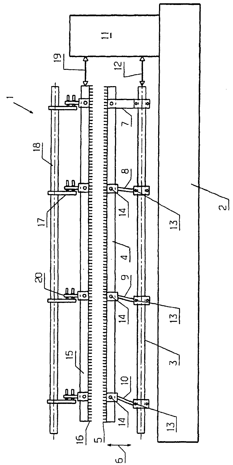
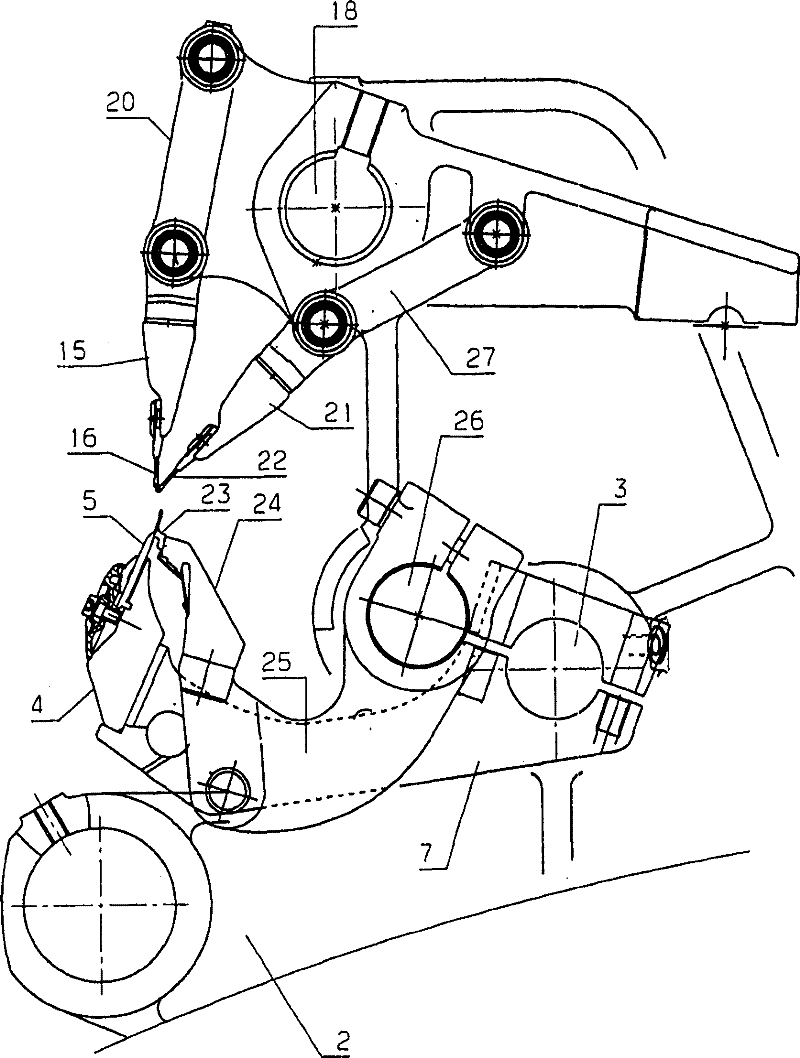
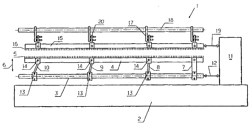
[0023] The warp knitting machine 1 has a frame 2 in which a support shaft 3 is mounted in a manner not shown in detail. The support shaft 3 is made of steel or another metal, for example.

[0024] A knitting tool bar 4 is suspended on the support shaft 3, and a large number of knitting needles 5 are equipped with the knitting tool bar 4. For the production of fabrics not shown in detail, the knitting needle 5 must make a reciprocating movement in the direction of the double arrow 6 during each looping process, that is, in the direction of the double arrow 6. figure 1 Make up and down movements.

[0025] The bearing shaft 3 is designed as a continuous bearing shaft. The support shaft 3 is connected with the knitting tool bar by a plurality of support rods 7-10. In this regard, the support bar 7 arranged on the end of the looping tool bar 4 adjacent to the jacquard drive 11 is designed as a fixed bar, that is, the fixed bar 7 does not allow the support shaft 3 and the looping...


PUM


Abstract

The present invention relates to a warp knitting machine (1), having at least a knitting tool bar (4) connected with a carrier shaft (3) by at least two carrying levers (8-10), where the tool bar and the carrier shaft exhibit different thermal expansion behaviors in a longitudinal direction. The objective of the invention is to control a problem caused by heating. Thereby, ends of at least one carrying levers (8-10) are shiftable relative to each other in the longitudinal direction.

Description

technical field [0001] The invention relates to a warp knitting machine, which has at least one knitting tool bar, and the knitting tool bar is connected to a support shaft through at least two support rods, wherein the knitting tool bar and the support The shafts have different thermal expansion characteristics in the longitudinal direction. Background technique [0002] Knitting tools can be needles, sliders, pile sinkers, etc., that is, almost any element that participates in the knitting process. But in the present case, the guide needle is not considered. [0003] When making fabric, the loop forming tool bar of a warp knitting machine must move back and forth essentially in one direction. The needle bars must, for example, be moved up and down. This movement is produced by the back and forth rotating bearing shaft, which is transmitted to the loop forming tool bar via the bearing rod. [0004] The looping tool bar should have as little mass as possible. The suppor...

Claims


Application Information

Patent Timeline
Patent Type & Authority Patents(China)
IPC IPC(8): D04B27/00
CPCD04B27/24D04B27/06
Inventor R・坎帕O・弗兰克
Owner KARL MAYER TEXTILMASCHFAB GMBH
Why Eureka
Try Eureka