Bonding material, process for producing the same, and honeycomb structure made with the same

Active Publication Date: 2008-10-09
NGK INSULATORS LTD
View PDF21 Cites 25 Cited by
  • Summary
  • Abstract
  • Description
  • Claims
  • Application Information

AI Technical Summary

Benefits of technology

[0013]The present invention has been made in view of the problem of the Prior Art described above, and an object of the invention is to provide a bonding material, which can form a bonding material layer of a high Young's Modulus, and attain a low expansion as well; and, therefore, the deformation of a honeycomb segment caused by generated thermal stress can

Problems solved by technology

At this regeneration time of the filter, there has been a problem that a large thermal stress is generated to cause a defect such as a crack and breakage.
However, in the sealing member (bonding material layer) used for the ceramic structure (honeycomb structure) disclosed in the Patent Document 1, there has been a problem that securement of a bonding strength between the segment and bonding material layer boundary surface and securement of a stress relaxation function of the bonding material layer itself are hard to be compatible in the uniform system realized

Method used


Image

  • Bonding material, process for producing the same, and honeycomb structure made with the same
  • Bonding material, process for producing the same, and honeycomb structure made with the same
  • Bonding material, process for producing the same, and honeycomb structure made with the same

Examples


Example

Example 1

Manufacture of Honeycomb Segment

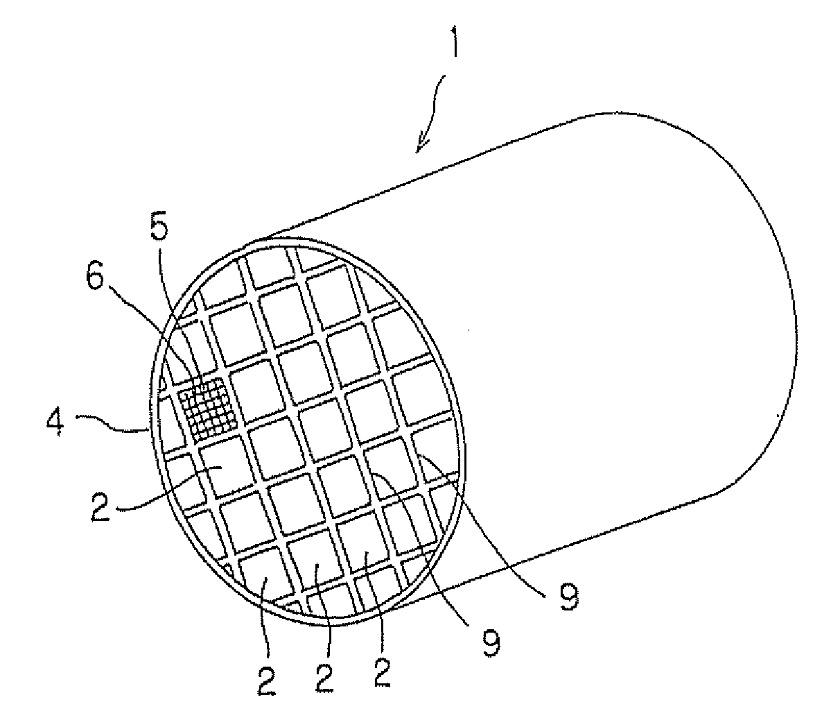
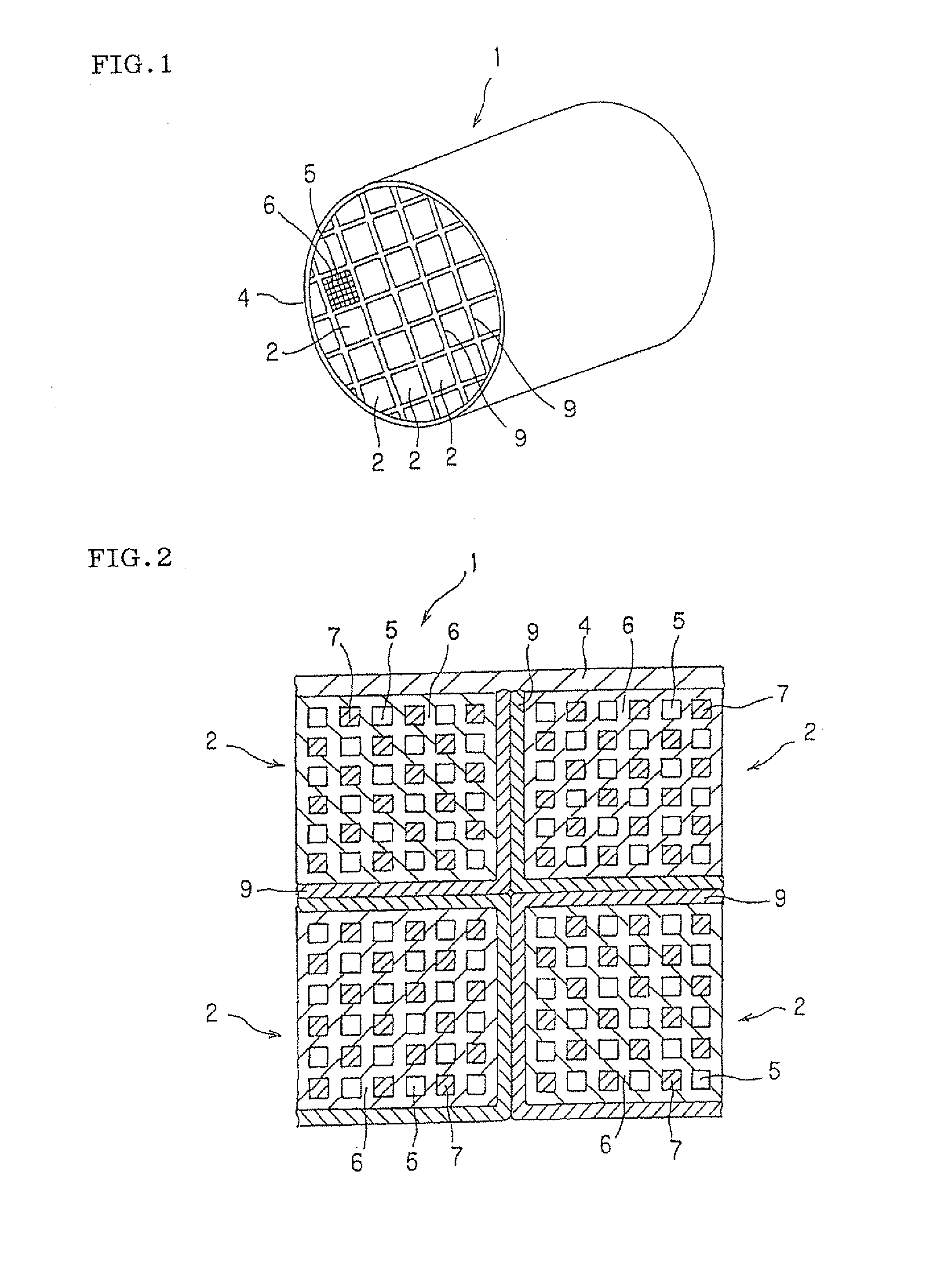
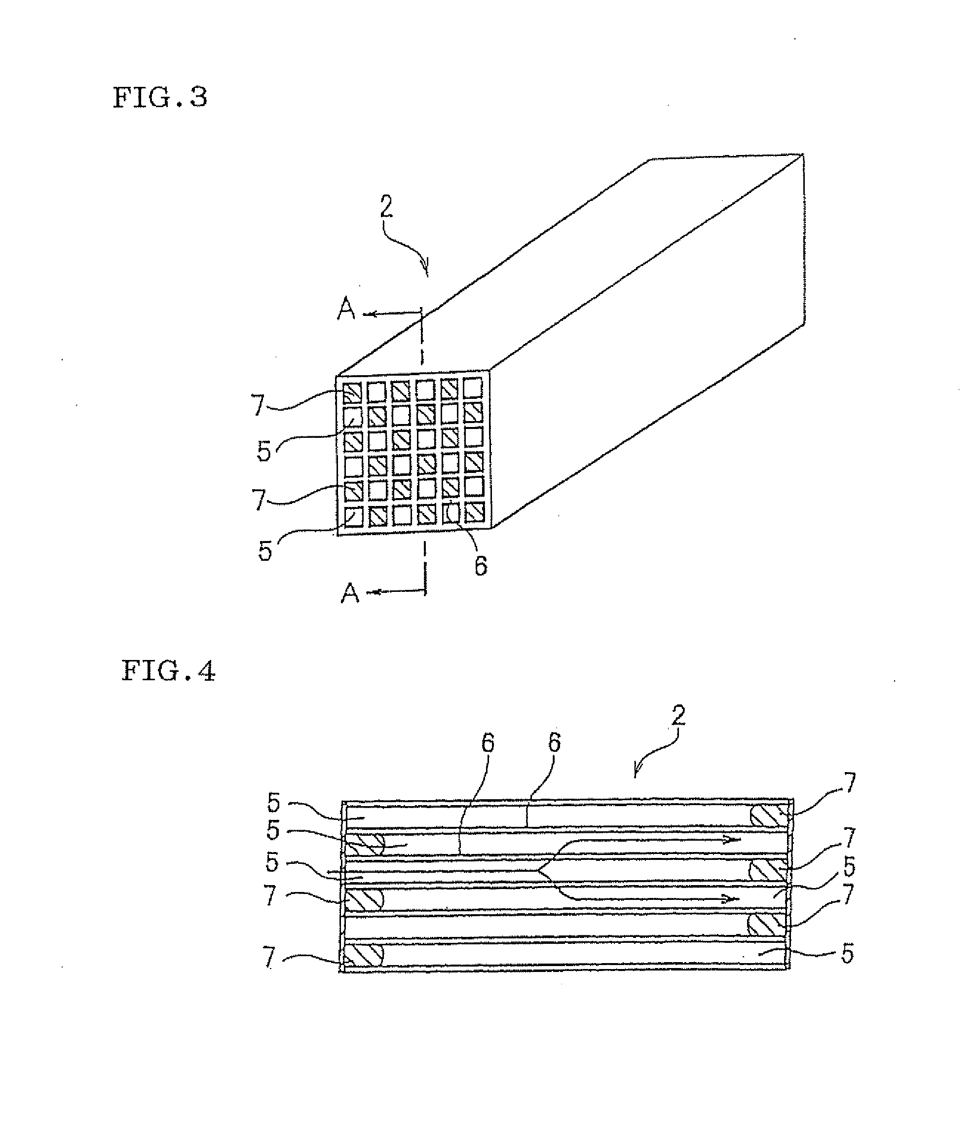
[0067]As a raw material of the honeycomb segment, SiC powder and metal Si powder were mixed at the mass ratio of 80:20, and to this mixed powder were added a pore formed material, an organic binder, a surface active agent, and water to prepare clay having plasticity. This kneaded clay was subjected to extrusion forming and the formed article was dried, so that a honeycomb segment dried article having a partition wall thickness of 310 μm, a cell density of approximately 46.5 cells / cm2 (300 cells / square inch), a regular square of 35 mm in one side of the cross-section, and a length of 152 mm was obtained. This honeycomb segment formed body was plugged at both end surfaces so that the end surface exhibits checkered patterns. That is, the adjacent cells were plugged so as to be mutually plugged at the ends of opposite sides. As the plugging material, the material similar to the honeycomb segment raw material was used. The honeycomb segment formed...

Example

Examples 2 to 11 and Comparative Examples 1 and 2

[0084]In Examples 2 to 11, honeycomb structures were manufactured in the same manner as in Example 1 except that the bonding material in Example 1 was changed to the bonding material compositions Nos. 2 to 11, respectively, shown in Table 1. Further, in Comparison Examples 1 and 2, honeycomb structures were manufactured in the same manner as in Example 1 except that the bonding material composition in Example 1 was changed to Nos. 12 and 13, respectively. Evaluation and Test were conducted in the same manner as in Example 1 on each of the obtained honeycomb structures (Examples 2 to 11 and Comparative Examples 1 and 2). The results are shown in Table 1.

TABLE 1Average linearNo ofFiller'sFiller's averagethermal expansionFiller's volumebondingYoung'slinear thermalcoefficient ratiofriction inmaterialMatrix'smodulusexpansion co-between fillerbondingcompositionFiller's typetype(GPa)efficient (×10−6K−1)& bonding materialmaterial (%)Others (m...

Example

Examples 1-11 and Comparative Examples 1 and 2

[0085]From the results of Table 2, in Examples 1 to 11, Young's Modulus of the bonding material is not less than 20% of the article to be bonded in, and the average linear coefficient of thermal expansion of the bonding material is not more than 70% of the articles to be bonded, and, therefore, no crack was observed in the honeycomb structure after the tests of various types were conducted.


PUM

PropertyMeasurementUnit
Temperatureaaaaaaaaaa
Fractionaaaaaaaaaa
Fractionaaaaaaaaaa

Abstract

There is provided bonding material having a Young's Modulus after hardening of not less than 20% of articles to be bonded, and an average linear coefficient of thermal expansion after hardening of not more than 70% of the articles to be bonded. This bonding material can suppress deformation of a honeycomb segment due to thermal stress to be generated by a bonding material layer and can suitably be used at the time of manufacturing exhaust gas trapping filters capable of reducing the generation of defects such as a crack, and above all, a diesel particulate filter (DPF) for trapping particulate matter (particulates) in exhaust gas from the diesel engine.

Description

TECHNICAL FIELD[0001]The present invention relates to a ceramic structure where a plurality of ceramic members are bonded together, and in particular, it relates to a bonding material used for bonding integrally a plurality of honeycomb segments to form a honeycomb structure.BACKGROUND ART[0002]A honeycomb structure is built into an exhaust system of a diesel engine and the like to be used as a trapping filter for exhaust gas, for example, as a diesel particulate filter (DPF) to trap and remove particulate matter (particulates) contained in an exhaust gas from the diesel engine and the like.[0003]Such a honeycomb structure has a structure in which a plurality of cells functioning as flow channels of fluid partitioned and formed by porous partition wall made of, for example, silicon carbide (SiC) are disposed in parallel with one another in the direction to the central axis. Further, ends of adjacent cells are alternately plugged (in a checkered pattern). That is, in one cell, one en...

Claims


Application Information

Patent Timeline
IPC IPC(8): B32B3/12C04B35/00
CPCB01D46/0001Y10T428/24149B01D46/2444B01D46/2448B01D46/2459B01D2046/2496B01D2265/04C04B35/10C04B35/185C04B35/195C04B35/478C04B35/563C04B35/565C04B35/581C04B35/584C04B35/597C04B37/005C04B38/0019C04B2111/00793C04B2237/06C04B2237/062C04B2237/068C04B2237/365B01D46/2429C04B38/0074B01D46/2498B01D46/24494B01D46/2478B01D46/24495C04B37/00B01D46/00
Inventor TOMITA, TAKAHIROFUJITA, HIROKI
Owner NGK INSULATORS LTD
Why Eureka
Try Eureka