
Roller alignment device and roller alignment method

A roller and stacking technology, which is applied in the field of roller stacking devices, can solve the problems such as the inclination and falling off of the roller R, and achieve the effect of realizing the stacking time and shortening.

Inactive Publication Date: 2014-04-09
NSK LTD
View PDF8 Cites 2 Cited by
  • Summary
  • Abstract
  • Description
  • Claims
  • Application Information

AI Technical Summary

Problems solved by technology

However, even when the retainer is used, the roller R may tilt or fall off in the state immediately after the roller set G is assembled and before the retainer is inserted.

Method used


Image

  • Roller alignment device and roller alignment method
  • Roller alignment device and roller alignment method
  • Roller alignment device and roller alignment method

Examples


Embodiment Construction

[0045] [First example of embodiment]

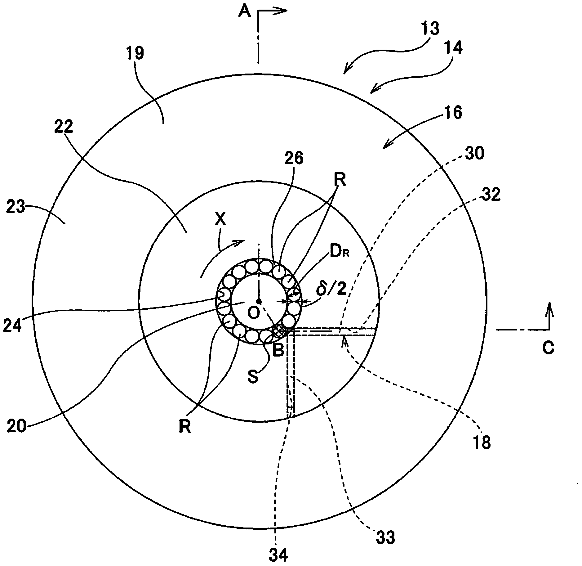
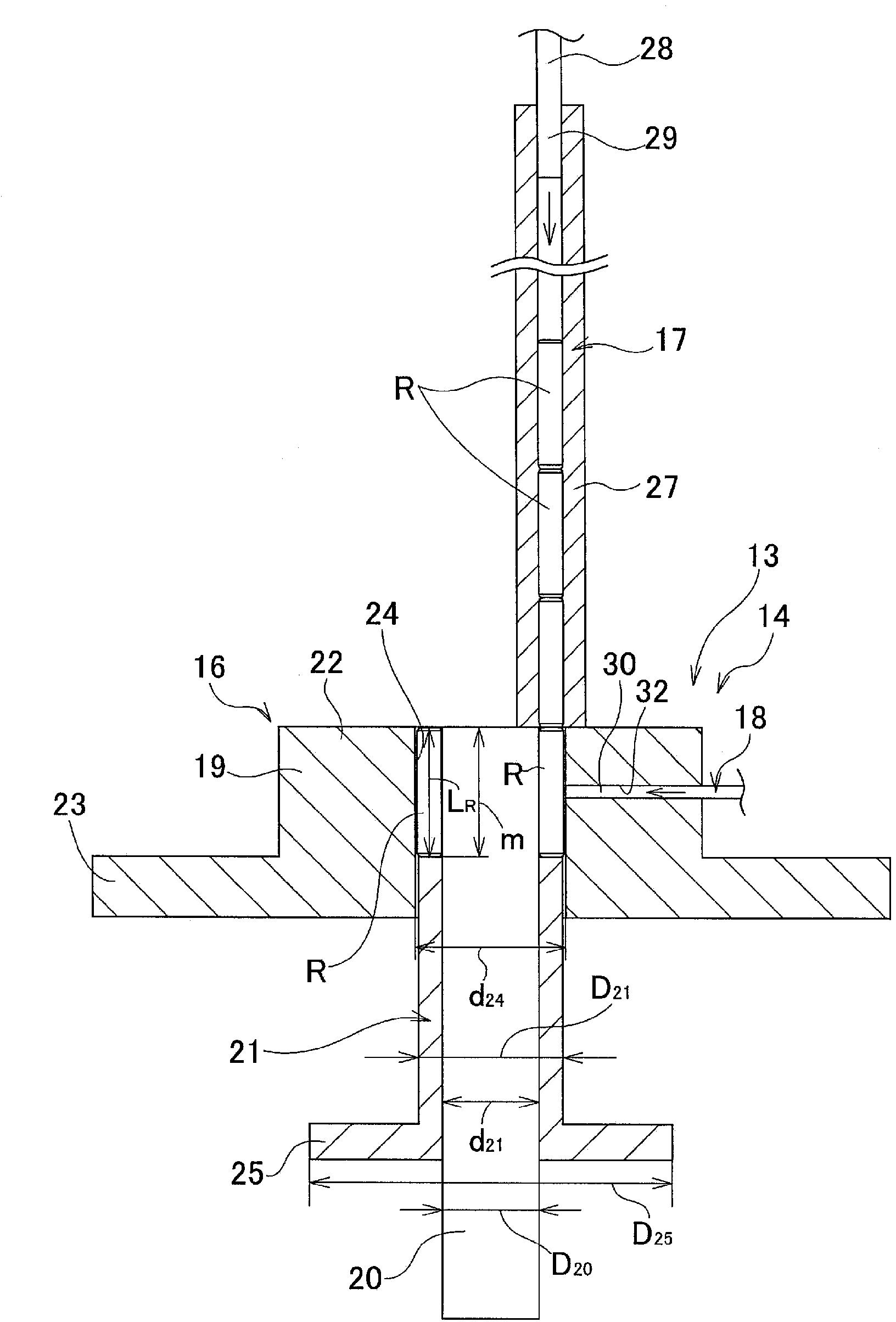
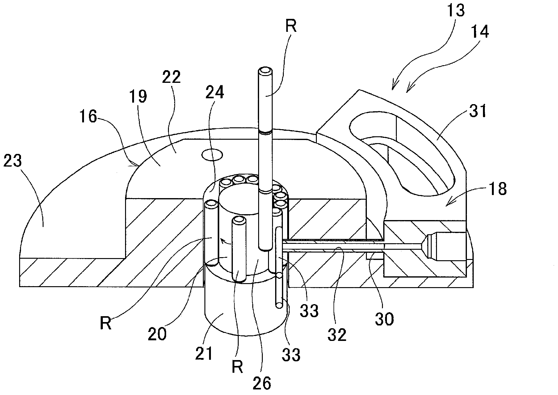
[0046] Figure 1 to Figure 8 The first example of the embodiment of the present invention is shown. The assembly device 13 is composed of a stacking device 14 and an insertion tool 15 for assembling a plurality of rollers R inside the outer ring W constituting the full complement radial roller bearing.

[0047] The stacking device 14 of the present invention has a tool body 16 , a roller supply part 17 and a stacking fluid supply part 18 . The tool body 16 is composed of a guide cylinder 19, a guide shaft 20, an extruding tool 21, and a cover (not shown). The part surrounded by these members forms a space with a predetermined space for stacking a plurality of rollers side by side. Shaped stacking space 26.

[0048] The guide cylinder 19 has a stepped cylindrical shape, and is composed of a thick portion 22 on the inner diameter side half and a thinner portion 23 on the outer diameter side half. A through hole 24 penetrating in the axi...


PUM


Abstract

The present invention aligns rollers (R) parallel to each other in an annular alignment space (24) while preventing damage from arising at the rolling surface of the rollers (R). In an annular alignment space (24) formed at a jig main body (14), a plurality of rollers (R) are sequentially supplied disposed in series in the axial direction in a direction matching the widthwise direction of the alignment space (24). By means of an alignment fluid supply means (16), air is jetted from a direction perpendicular to the direction of supply of rollers (R) at the roller (R) at the supply position of the alignment space (24), moving the roller (R) in the peripheral direction of the alignment space (24), and the next roller (R) is supplied into the alignment space (24), thus aligning the plurality of rollers (R) parallel to each other in an annular shape.

Description

technical field [0001] The present invention relates to a roller stacking device for stacking rollers in an annular shape in order to assemble the rollers inside an outer ring constituting the roller bearing, etc., used when assembling a roller bearing having a plurality of rollers, and Roller stacking method. Background technique [0002] A radial roller bearing is incorporated into a rotation support portion for supporting a large radial load and supporting a rotation shaft. When the rotation support needs to support a larger radial load, a so-called full complement radial roller bearing is used in which the load capacity is increased without providing a cage. [0003] In order to assemble radial roller bearings of the full complement roller type, various assembly devices and tools (Japanese: jigs) have been used in the past. Figure 11 It shows the assembly apparatus of the conventional structure described in Unexamined-Japanese-Patent No. 5-329721. The assembly device ...

Claims


Application Information

Patent Timeline
Patent Type & Authority Applications(China)
IPC IPC(8): B23P21/00B23P19/00F16C19/26F16C43/06
CPCB23P21/00F16C43/06F16C19/26B23P19/04B23P19/00B23P19/001F16C19/46Y10T29/49679Y10T29/49682Y10T29/53104B23P19/10
Inventor 长崎雄一
Owner NSK LTD
Learn More