Device and method for forming gear through rotary swaging in radial direction

A gear and forging die technology, which is applied in the field of gear radial swaging forming devices, can solve the problems of low forming precision and large load, and achieve the effects of improving forming precision and tooth strength, improving material utilization, and strong reliability

Active Publication Date: 2014-04-16
福建祥鑫股份有限公司
View PDF7 Cites 7 Cited by
  • Summary
  • Abstract
  • Description
  • Claims
  • Application Information

AI Technical Summary

Problems solved by technology

[0005] The present invention provides a gear radial swaging forming device and method in order to solve the problems of low forming precision and large required load in traditional precision forging gears which adopt axial overall loading.

Method used


Image

  • Device and method for forming gear through rotary swaging in radial direction
  • Device and method for forming gear through rotary swaging in radial direction
  • Device and method for forming gear through rotary swaging in radial direction

Examples


specific Embodiment approach 1

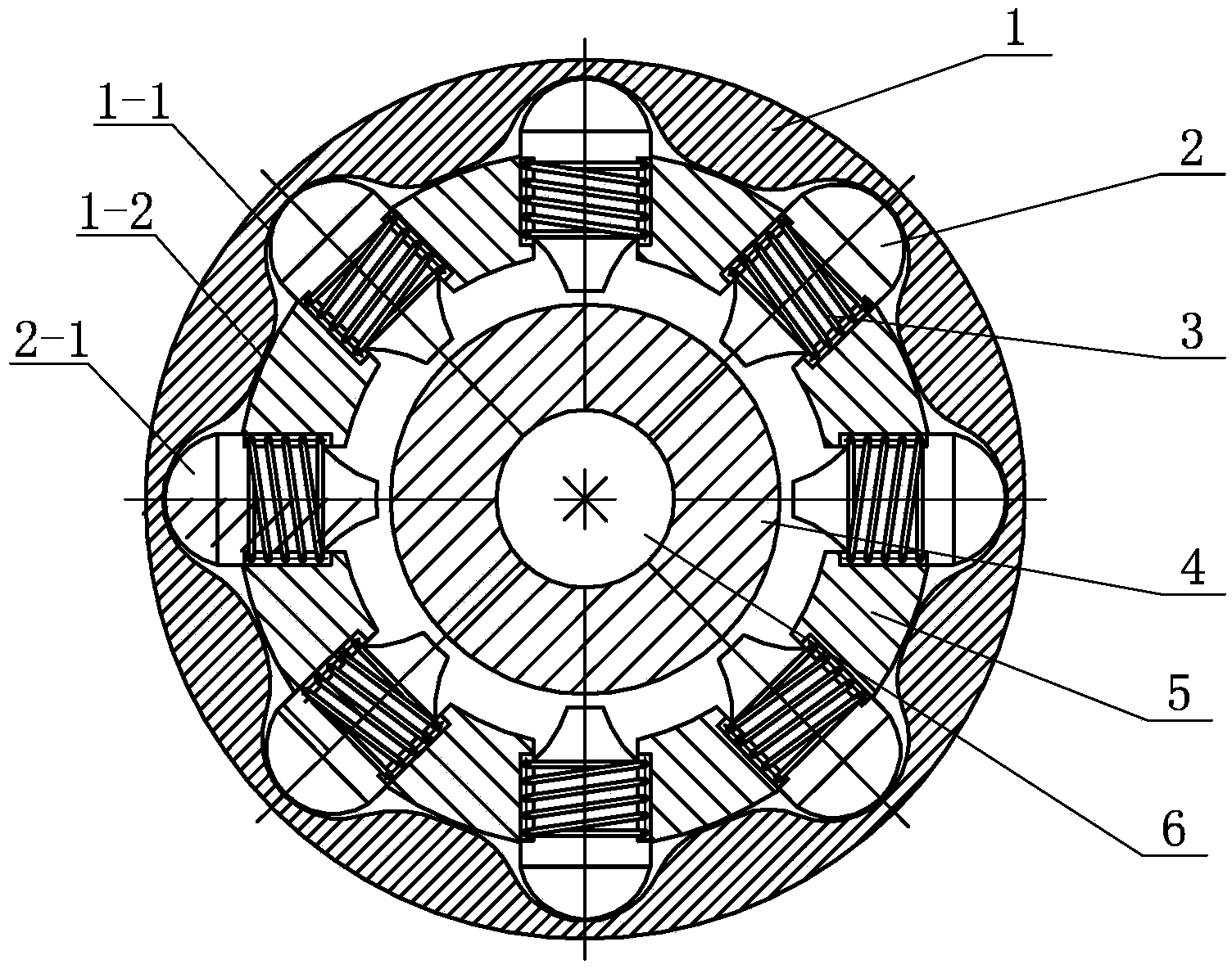
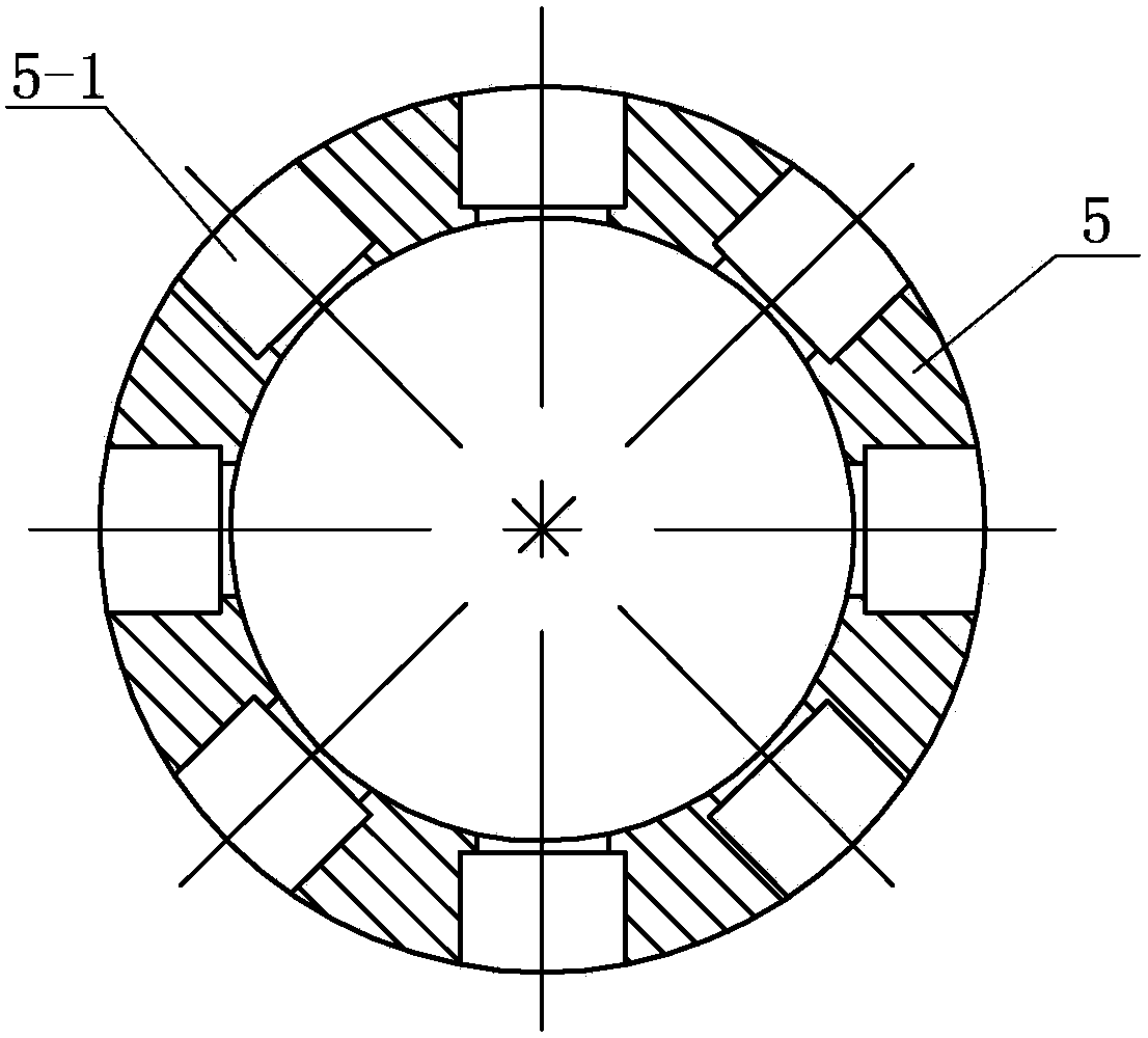
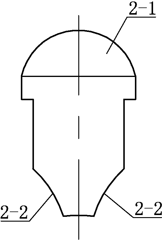
[0027] Specific implementation mode one: combine Figure 1 ~ Figure 4 Describe this embodiment. This embodiment includes a swaging die 1, a spring 3, a guide die 5, a mandrel 6 and several radial punches 2. The inner wall of the swaging die 1 is evenly arranged with several arc grooves 1 along the circumference. -1 and several protrusions 1-2, several arc grooves 1-1 and several protrusions 1-2 are arranged alternately, the number of arc grooves 1-1 is the same as the number of radial punches 2, One end of the radial punch 2 is an arc head 2-1, and the other end of the radial punch 2 is symmetrically provided with an inward concave arc 2-2 based on the axis line of the radial punch 2, so The guide die 5 is evenly distributed along the circumference with stepped holes 5-1 equal to the number of radial punches 2, and the radial punches 2 with springs 3 on the bottom are respectively put into each stepped hole 5-1, and the springs 3, The assembly of the radial punch 2 and the gu...

specific Embodiment approach 2

[0028] Specific implementation mode two: combination image 3 and Figure 5 To describe this embodiment, the radian of the concave arc 2-2 in this embodiment is the same as the radian of the tooth profile of the gear to be machined. Other components and connections are the same as those in the first embodiment.

specific Embodiment approach 3

[0029] Specific implementation mode three: combination figure 1 , Figure 5 and Figure 6 Describe this implementation mode, this implementation mode is realized through the following steps:

[0030] Step 1. Set the to-be-processed circular blank 4 on the mandrel 6;

[0031] Step 2. Rotate the swaging die 1 clockwise or counterclockwise for 1 / 2N (one part of 2N) circle, N is the number of punches;

[0032] Step 3. During the rotation process, the protrusion 1-2 on the swaging die 1 exerts pressure on the arc head 2-1, and the radial punch 2 gradually moves toward the center of the mandrel 6 along the stepped hole 5-1 of the guide die 5. The axis moves, and while the spring 3 is compressed, the radial punch 2 exerts radial pressure on the blank 4;

[0033] Step 4. When the swaging die 1 rotates until the center of the protrusion 1-2 coincides with the axial center of the radial punch 2 (see Figure 5 ), that is, the end of the forming of a blank;

[0034] Step 5. Continue...


PUM


Abstract

The invention provides a device and method for forming a gear through rotary swaging in the radial direction, and relates to a gear forming device and method to solve the problems that when axial overall loading is adopted for a traditional gear obtained through finish forging, forming accuracy is low, and required loads are large. According to the device, a plurality of arc-shaped grooves in a rotary swaging die 1 and a plurality of protrusions in the rotary swaging die 1 are alternately arranged, radial punch pins with springs arranged at the bottom in a sleeved mode are placed in stepped holes respectively, and the radial punch pins and components of a guide die are arranged in the rotary swaging die. The method includes the steps that firstly, a blank to be machined is arranged on a mandrel in a sleeved mode; secondly, the rotary swaging die rotates by 1 / 2N circles in the clockwise direction or the anti-clockwise direction; thirdly, in the rotating process, the protrusions exert pressure on an arc-shaped head, and the radial punch pins move gradually towards the axis of the mandrel along the stepped holes; fourthly, when the rotary swaging die rotates to the centers of the protrusions and coincides with the axes of the punch pins, the forming process is completed; fifthly, the rotary swaging die continues to rotate by 1 / 2N circles in the clockwise direction or the anti-clockwise direction, the radial punch pins retreat to the initial positions, and then the forged gear part can be taken out. The device and method are used for forming the gear.

Description

technical field [0001] The invention relates to a gear forming device and method, in particular to a gear radial swaging forming device and method. Background technique [0002] Gears are one of the important components in automobile gearboxes and various mechanical power transmission systems. The quality and performance of gears have a decisive impact on the stability and reliability of the entire system. Therefore, the research on gear processing methods and the improvement of comprehensive performance have always been the focus of widespread attention in the industry. The traditional manufacturing of gears is mainly based on cutting processing, but the bottleneck problems such as low material utilization rate, low production efficiency and high cost cannot meet the actual needs of current production enterprises and users. [0003] Gear precision forging is a processing method with little or no cutting. The precision forging technology achieves the processing goal of near...

Claims


Application Information

Patent Timeline
Patent Type & Authority Applications(China)
IPC IPC(8): B21K1/30B21J5/06
Inventor 李峰李巍李润江
Owner 福建祥鑫股份有限公司
Why Eureka
Try Eureka