Spindle structure

A technology for spindles and angular contact ball bearings, which is applied in the direction of large fixed members, metal processing machinery parts, metal processing equipment, etc., can solve the problems of complicated spindle transmission, etc., and achieve the advantages of fewer stages of spindle transmission, simple structure of the spindle and low noise Effect

Inactive Publication Date: 2014-04-16
WUXI JINGHUA HEAVY IND EQUIP MFG
View PDF5 Cites 2 Cited by
  • Summary
  • Abstract
  • Description
  • Claims
  • Application Information

AI Technical Summary

Problems solved by technology

[0003] In the prior art, the transmission of the main shaft is cumbersome, so it is particularly necessary to optimize the structure of the main shaft

Method used


Image

  • Spindle structure

Examples


Embodiment Construction

[0009] The present invention will be further described below in conjunction with specific drawings and embodiments.

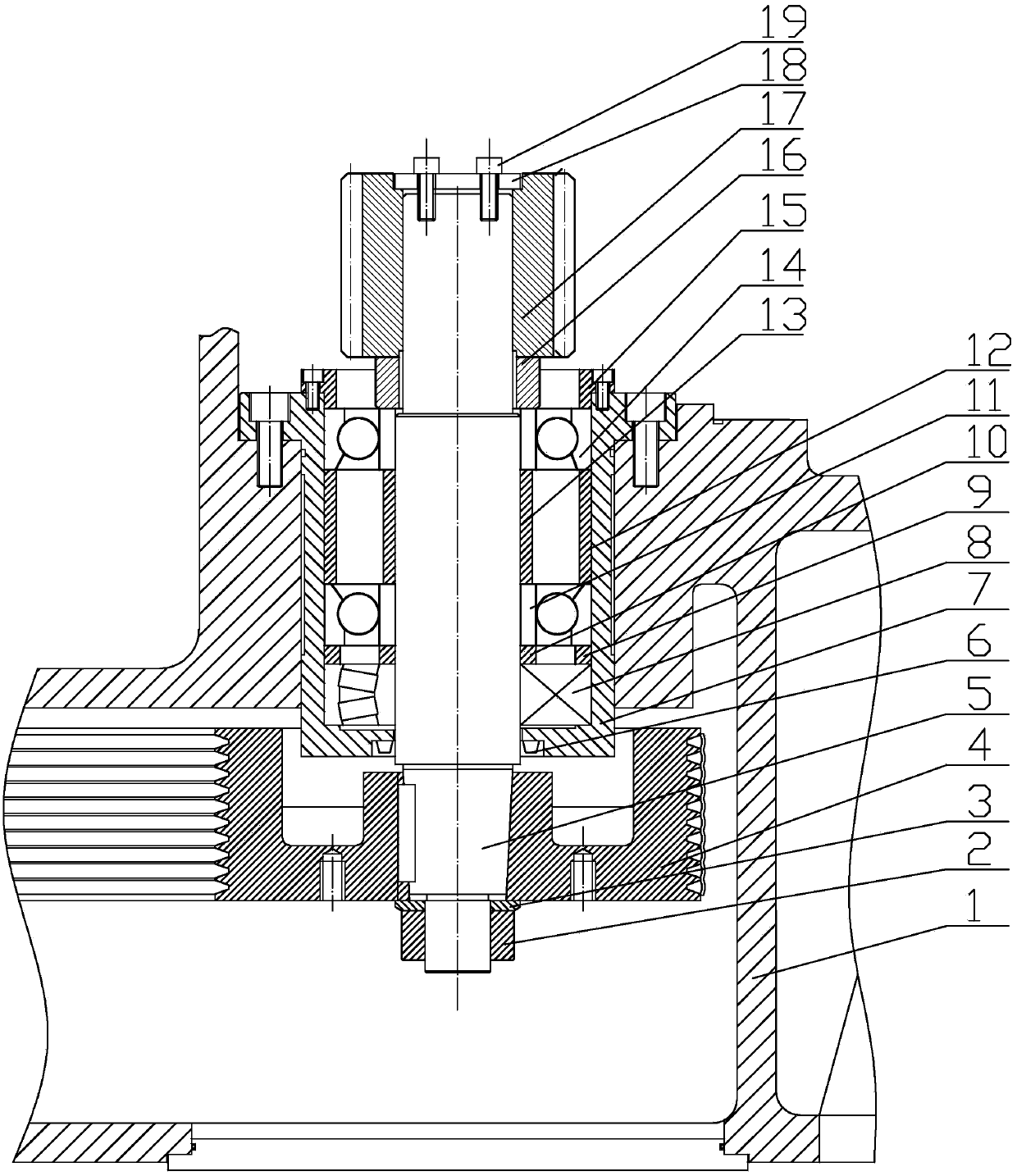
[0010] Such as figure 1 As shown, table base 1, lock nut 2, spacer 3, pulley 4, main shaft 5, frame oil seal 6, first flange 7, spherical roller bearing 8, first spacer 9, second spacer Sleeve 10, first angular contact ball bearing 11, third spacer 12, fourth spacer 13, second angular contact ball bearing 14, second flange 15, fifth spacer 16, gear 17, gland 18 And bolt 19.

[0011] Such as figure 1 As shown, the present invention is a spindle structure, including a workbench base 1, a flange 7 arranged on the workbench base 1, and fixed with bolts. The spherical roller bearing 8, the first spacer 9, the second spacer 10, the first angular contact ball bearing 11, the third spacer 12, and the fourth spacer are sequentially installed on the first flange 7. 13. The second angular contact ball bearing 14, then press it with the second flange 15, fix the second...


PUM


Abstract

The invention provides a spindle structure. A first flange plate is arranged on a worktable base, the first flange plate is sequentially provided with a centering roller bearing, a first spacer, a second space, a first angular contact ball bearing, a third spacer, a fourth spacer and a second angular contact ball bearing, then the first flange plate is pressed with a second flange plate, the second flange plate is fixed to the first flange plate, and then a spindle is installed into the second flange plate; a fifth spacer is arranged on the upper portion of the spindle, then a gear is arranged in the fifth spacer, and a gland is used for pressing the gear and a spindle head; a belt wheel is arranged on the lower portion of the spindle and is pressed through the spacers and a fastening nut. The spindle structure is simple, ingenious, reasonable, uniform and stable in transmission process, low in noise, stable and reliable, and transmission series of the spindle are reduced.

Description

technical field [0001] The invention relates to a spindle structure, which is especially suitable for vertical lathes and belongs to the technical field of mechanical equipment. Background technique [0002] The vertical lathe is mainly used to process large and heavy workpieces with large diameter and short length and workpieces that are not easy to clamp on a horizontal lathe. When the rotary diameter is sufficient, it is difficult to clamp too heavy workpieces on a horizontal lathe. Due to its own weight, it is difficult for processing The accuracy is affected, and the above problems can be solved by using vertical lathe. [0003] In the prior art, the transmission of the main shaft is cumbersome, so it is particularly necessary to optimize the structure of the main shaft. Contents of the invention [0004] The purpose of the present invention is to overcome the deficiencies in the prior art, and provide a main shaft structure, which is simple, ingenious and reasonable...

Claims


Application Information

Patent Timeline
Patent Type & Authority Applications(China)
IPC IPC(8): B23B19/02
CPCB23Q1/70
Inventor 朱振强
Owner WUXI JINGHUA HEAVY IND EQUIP MFG
Why Eureka
Try Eureka