Machining clamp for automobile steering knuckle flange end face holes

A technology for automobile steering knuckle and end face, which is applied in the direction of manufacturing tools, metal processing equipment, metal processing machinery parts, etc., can solve the problems of low production efficiency, high labor intensity and high production cost

Inactive Publication Date: 2014-04-16
曹立新 +3
View PDF0 Cites 10 Cited by
  • Summary
  • Abstract
  • Description
  • Claims
  • Application Information

AI Technical Summary

Problems solved by technology

[0002] Under the premise of not changing the technical requirements for ensuring the position of the flange end face porous relative to the shaft reference and the end face reference, the invention of the processing fixture for the end face hole of the steering knuckle parts completely replaces the original old-fashioned flip-type drilling jig for Solve the processing problems of low production efficiency, high labor intensity and high production cost

Method used


Image

  • Machining clamp for automobile steering knuckle flange end face holes

Examples


Embodiment Construction

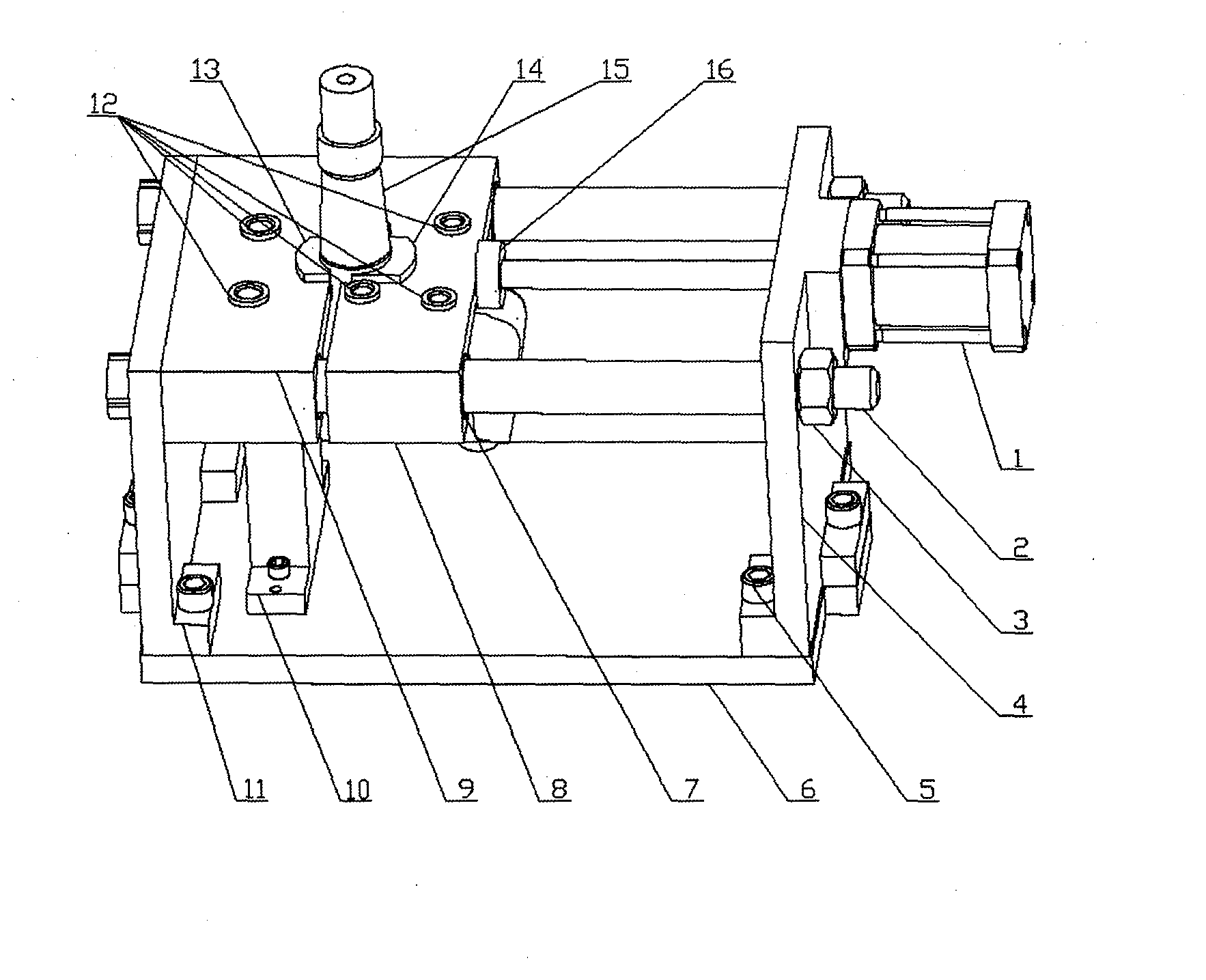
[0009] combined with figure 1 As shown, the fixture design adopts the face-up flip-up automatic compression method of the workpiece flange. When the hydraulic cylinder (piece 1) shrinks, the coupling nut (piece 16) at the end of the hydraulic rod drives the movable drilling template (piece 8) to slide and separate along the two guide rods (piece 2), and the shaft of the workpiece goes upward, and the movable template (piece 8) is put into the moving template (piece 2). 8) Between the fixed template (piece 9), the ear of the workpiece is placed on the V-shape of the orientation seat (piece 10). The hydraulic device pushes the movable drilling template and the half ring connected to the drilling template to automatically correct the workpiece shaft and hold it tightly on the half ring of the fixed drilling template to complete the clamping work. Start the main shaft of the machine tool, and the drill bit drills the workpiece along the drill cover (piece 12).

[0010] This new ...


PUM


Abstract

The invention discloses a machining clamp for automobile steering knuckle flange end face holes. On the premise that original technical requirements are met, the machining clamp utilizes the technical characteristic that a shaft part of a part and the end face of a flange are mutually perpendicular, positioning is performed with an accurate reference shaft diameter, it is guaranteed that the axis is perpendicular to drill plates, the flange end face is in a parallel state, and the technical requirements are effectively guaranteed. According to the design of the novel clamp, the two separable drill plates are adopted, when the movable drill plate is pulled open by a hydraulic device, a workpiece is placed between the fixed drill plate and the movable drill plate, the hydraulic device pushes half rings in linkage with the movable drill plate and the fixed drill plate to automatically correct the shaft part of the workpiece along two guide rods and hoop the shaft part on the half ring of the fixed drill plate, so that clamping work is finished. It is sufficiently guaranteed that the two drill plates are in parallel under the limit of the two guide rods, the shaft part is completely kept perpendicular after the workpiece is compressed by the drill plates in parallel, the fixed drill plate is kept still, positioning half rings connected with the drill plates always keep the center of the part unchanged, and therefore the technical requirements are met. Due to the fact that one-off hydraulic clamping is adopted, the time for clamping the part is reduced, one worker can achieve multi-machine operation through an automatic numerical control machining tool, and therefore production cost is reduced.

Description

technical field [0001] The invention relates to an automobile steering knuckle and various parts that must be positioned by the shaft and processed vertically from the direction of the shaft. Background technique [0002] Under the premise of not changing the technical requirements for ensuring the position of the flange end surface porous relative to the shaft reference and the end surface reference, the invention of the processing fixture for the end surface hole of the steering knuckle parts completely replaces the original old-fashioned flip-type drilling jig for Solve the processing problems of low production efficiency, high labor intensity and high production cost. Contents of the invention [0003] The design drawing of the invention fixture is attached figure 1 shown. 1. Hydraulic cylinder (1 piece), 2. Guide rod (2 pieces), 3. Nut (2 pieces), 4. Support plate (1 piece), 5. Screws (8 pieces), 6. Base (1 piece) , 7. Guide sleeve (2 pieces), 8. Movable drilling t...

Claims


Application Information

Patent Timeline
Patent Type & Authority Applications(China)
IPC IPC(8): B23Q3/00B23B47/28
CPCB23B47/28B23B2247/12B23B2247/14
Inventor 曹立新
Owner 曹立新
Why Eureka
Try Eureka