Machine tool equipped with cutting fluid filtering device

A filtration device and cutting fluid technology, which is applied in filtration and separation, fixed filter element filters, manufacturing tools, etc., can solve the problems of unconsidered, ineffective use of compressed air pressure, insufficient effect, etc., to improve the effect of backwashing Effect

Inactive Publication Date: 2014-04-16
FANUC LTD
View PDF4 Cites 8 Cited by
  • Summary
  • Abstract
  • Description
  • Claims
  • Application Information

AI Technical Summary

Problems solved by technology

However, this document only records that the timing of the switch of the switch valve provided on the water supply pipe and the switch of the switch valve provided on the air supply pipe can be adjusted by using the control device. The on-off valve on the water supply pipe and the on-off valve on the air supply pipe are opened and closed at the same time
[0013] In the above prior art documents, there is no consideration of when to open the discharge pipe after the compressed air is supplied to the filter for backwashing, so the pressure of the compressed air cannot be effectively used, especially to remove the air entering the filter. Insufficient effect of chips

Method used


Image

  • Machine tool equipped with cutting fluid filtering device
  • Machine tool equipped with cutting fluid filtering device
  • Machine tool equipped with cutting fluid filtering device

Examples


Embodiment Construction

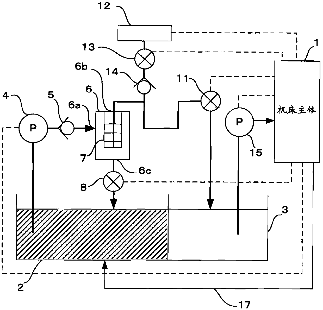
[0031] First, use figure 1 A first embodiment of the cutting fluid filter device will be described.

[0032] Symbol 1 is the main body of the machine tool with the control device, 2 is the sewage tank, 3 is the clean water tank, 4 is the filter pump, 5 is the check valve installed behind the filter pump when viewed from the flow direction of the cutting fluid, and 6 is the filter pump. container. The filter container 6 is provided with an inflow port 6a for the cutting fluid from the filter pump 4, an opening 6b through which the cutting fluid flows out during filtering and air flows during backwashing, and an opening 6b through which air or cutting fluid is discharged during backwashing. The discharge port 6c is provided with a filter 7 inside the filter container 6 . In addition, reference numeral 8 is a backwash discharge valve, 11 is a clean water tank valve, 12 is an air source, 13 is an air supply pump, and 14 is a check valve installed on the downstream side of the a...


PUM


Abstract

A filter which is used to remove chips and sludge produced by the processing using a machine tool is backwashed. At this time, a valve provided in an outlet of a filter container is opened based on an elapse time from the start of the supply of compressed air or a cutting fluid to the filter container or a detection value of a pressure inside the filter container. In this way, the supply pressure of the cutting fluid or the compressed air is sufficiently applied to the filter, so that chips adhering to a surface of the filter are sufficiently removed.

Description

technical field [0001] The present invention relates to a machine tool provided with a cutting fluid filtering device, wherein the cutting fluid filtering device has a filter for backwashing a filter for removing chips or muddy deposits mixed in the cutting fluid due to machining of the machine tool cleaning function. Background technique [0002] In the processing of machine tools, impurities such as chips or mud-like deposits generated during processing are mixed into the cutting fluid, and as a result, the performance and reliability of the machine tool are adversely affected. Therefore, the removal of these chips or mud-like deposits filter. The filter is cleaned for the purpose of maintaining the purification performance of the filter and prolonging the life of the filter. In this filter cleaning, there is backwashing in which cutting fluid is flowed in a direction opposite to that of the cutting fluid during normal use, and chips and muddy deposits adhering to the fi...

Claims


Application Information

Patent Timeline
Patent Type & Authority Applications(China)
IPC IPC(8): B23Q11/10B01D35/16
CPCB23Q11/1069B01D35/02B01D29/661B01D29/668
Inventor 石原光告
Owner FANUC LTD
Why Eureka
Try Eureka