Shutter die

A shutter and mold technology, applied in metal processing and other directions, can solve the problems of large punching force, high processing cost, high noise, etc., and achieve the effect of reducing the punching force

Active Publication Date: 2014-04-16
GREE ELECTRIC APPLIANCES INC
View PDF15 Cites 5 Cited by
  • Summary
  • Abstract
  • Description
  • Claims
  • Application Information

AI Technical Summary

Problems solved by technology

[0002] At present, the processing and molding of shutters on the market requires two processes. For example, to process the shutters on the shell of the window machine and air conditioner, punch the opening first, and then turn the side to complete the production of the shutters. The punching method is line punching, and the tools used like Figure 1 to Figure 3 As shown, the punching force, noise, and vibration of this method are large during production, which is a difficult point in the production of sheet metal stamping. For example, a shutter with 40 pieces as a unit requires a punching force of about 150 tons. The noise is More than 110 decibels; and a window machine cover part, there are at most 14 units of shutters, so the total punching force is as high as 2100 tons, so there are a lot of equipment involved and a lot of punching times. At the same time, large punching force and punching eccentric load , It is easy to cause the loss of precision of the sliders of many punching machines, which can no longer be used in the production of shutters. Such predatory use of punching machines has a huge impact on punching machines, resulting in high processing costs and low processing efficiency

Method used


Image

  • Shutter die
  • Shutter die
  • Shutter die

Examples


Embodiment Construction

[0024] In order to make the objectives, technical solutions and advantages of the present invention clearer, the shutter mold of the present invention will be further described in detail below with reference to the accompanying drawings and embodiments. It should be understood that the specific embodiments described herein are only used to explain the present invention, but not to limit the present invention.

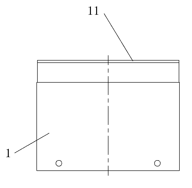
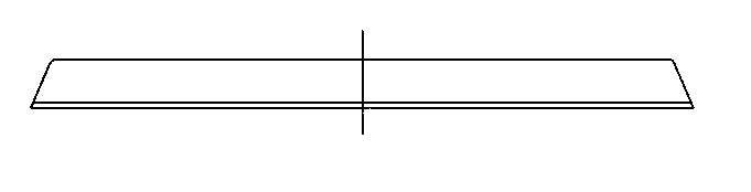
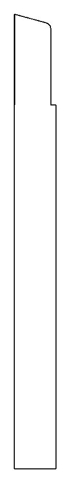
[0025] refer to Figure 4 to Figure 10 , an embodiment of the shutter mold of the present invention includes a punch 2 and a concave die 3, the punch 2 is fixedly mounted on an upper die base (not shown), and the upper die base is connected to the slider of the punch press, and the slider is connected with the slider. Moving up and down, the concave die 3 is fixed on the lower die base (not shown), the lower die base is fixed on the working table of the punch press, the concave die 3 is provided with a forming die 4, and the punch 2 is provided with at least one cutter...


PUM


Abstract

The invention discloses a shutter die which comprises a male die and a female die. The female die is provided with a forming die, the male die is provided with at least one cutter which is used for punching plates, the cutter is provided with a blade, and height difference exists between the first end and the second end of the blade. According to the shutter die, from the aspect of microscopic view, point-by-point cutting of the plates is achieved in short time, and the punching force, the noise and the vibration are lowered.

Description

technical field [0001] The invention relates to the field of molds, in particular to a shutter mold. Background technique [0002] At present, the processing and forming of the shutters on the market requires two processes. For example, the shutters on the housing of the window machine air conditioner are processed by punching first, and then flanging to complete the production of the shutters. The punching method is line punching. like Figure 1 to Figure 3 As shown in the figure, using this method in production has large punching force, high noise and large vibration, which is the production difficulty of sheet metal stamping. For example, a 40-piece shutter requires a punching force of about 150 tons, and the noise is in the More than 110 decibels; and a window cover part has a maximum of 14 units of shutters, so the total punching force is as high as 2,100 tons. Therefore, a lot of equipment is involved and the number of punching times is also large. At the same time, la...

Claims


Application Information

Patent Timeline
Patent Type & Authority Applications(China)
IPC IPC(8): B26F1/44B21D28/14
Inventor 张玉夔林建明陈志伟郭朝辉刘亚丁启飞
Owner GREE ELECTRIC APPLIANCES INC
Why Eureka
Try Eureka