Large-rigidity multi-connecting-rod controllable mechanical loading mechanism

A loading mechanism and multi-link technology, applied in mechanically driven excavators/dredgers, etc., can solve the problems of poor kinematics and dynamic performance, easy overload damage of mechanical transmission, difficult design and production of loader, etc. Overload resistance, superior kinematics and dynamics, compact structure

Inactive Publication Date: 2014-04-16
GUANGXI UNIV
View PDF6 Cites 14 Cited by
  • Summary
  • Abstract
  • Description
  • Claims
  • Application Information

AI Technical Summary

Problems solved by technology

The efficiency of mechanical transmission is high, and the existing mechatronics technology can overcome the shortcomings of mechanical transmission, such as easy overload damage
However, most of the existing multi-degree-of-freedom controllable loading mechanisms are simply improvements to the existing hydraulic loading mechanisms. The hydraulic system in the hydraulic loading mechanism is replaced by a two-link mechanism, which lacks the dynamic performance of rod transmission and hydraulic cylinder transmission. Considering the difference, it leads to disadvantages such as poor rigidity of the mechanism, small overload resistance, poor kinematics and dynamic performance, and it is difficult to meet the needs of actual operations. Although some deficiencies in the hydraulic system have been solved, it is difficult to apply to the design and production of loaders.

Method used


Image

  • Large-rigidity multi-connecting-rod controllable mechanical loading mechanism
  • Large-rigidity multi-connecting-rod controllable mechanical loading mechanism
  • Large-rigidity multi-connecting-rod controllable mechanical loading mechanism

Examples


Embodiment Construction

[0016] The technical solution of the present invention will be further described below with reference to the accompanying drawings.

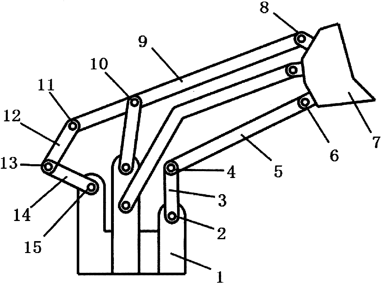
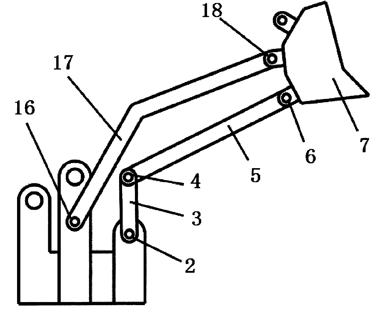
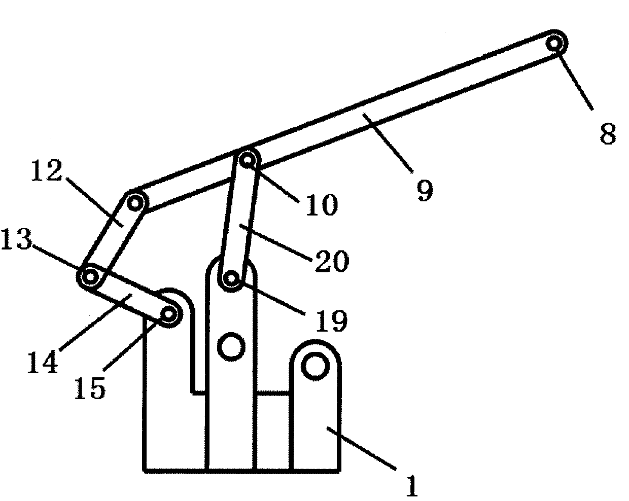
[0017] control figure 1 , figure 2 , image 3 , Figure 4 , a high-rigidity multi-link controllable mechanical loading mechanism is composed of a frame 1, a boom control branch chain, and a bucket control branch chain.

[0018] control figure 1 , figure 2 , the boom control branch chain is composed of the first active rod 3, the first connecting rod 5, the boom 17, and the bucket 7, and one end of the first active rod 3 is connected to the frame 1 through the first rotating pair 2, The other end is connected to the first connecting rod 5 through the second rotating pair 4, the first connecting rod 5 is connected to the bucket 7 through the third rotating pair 6, and one end of the boom 17 is connected to the frame 1 through the fourth rotating pair 16 , the other end is connected with the bucket 7 through the fifth rotating pair 18.

[...


PUM


Abstract

A large-rigidity multi-connecting-rod controllable mechanical loading mechanism comprises a frame, a movable arm control branch chain and a bucket control branch chain. The movable arm control branch chain is controlled by a first drive rod to perform movable arm ascending or descending. The bucket control branch chain is controlled by a second drive rod to control turning of a bucket. By cooperation of the movable arm control branch chain and the bucket control branch chain, loading operation can be completed. Rods of the mechanical loading mechanism are connected through rotating pairs, and the defects that traditional total-hydraulic loading mechanisms containing moving pairs are high in manufacturing cost, poor in reliability, high in maintenance cost and the like are overcome. Compared with other controllable mechanical loading mechanisms, the loading mechanism is compact in structure, high in rigidity, and good in reliability and dynamic stability by using the novel structure with excellent kinematic and dynamic performance.

Description

technical field [0001] The invention relates to the field of engineering machinery, in particular to a large-rigidity multi-link controllable mechanical loading mechanism. Background technique [0002] Loader is a kind of earthwork construction machinery widely used in construction projects such as roads, ports, mines, railways, etc. It is mainly used for shoveling bulk materials such as soil, sand and gravel, and can also be used for light shoveling of ore, hard soil, etc. Operation. Different auxiliary working devices can also be used for bulldozing, lifting and loading and unloading of other materials. Loaders are the most widely used construction machinery. With the development of social economy, loaders are more and more used in urban municipal engineering, garbage cleaning, construction engineering and other occasions. The existing loader is mainly composed of two parts: the boom lifting mechanism and the bucket turning mechanism, which are respectively controlled by...

Claims


Application Information

Patent Timeline
Patent Type & Authority Applications(China)
IPC IPC(8): E02F3/38
Inventor 蔡敢为张林关卓怀石慧王麾范雨王少龙杨旭娟李岩舟
Owner GUANGXI UNIV
Why Eureka
Try Eureka