
Hydraulic packer and installation method thereof

A packer and hydraulic technology, applied in the direction of sealing/isolation, earthwork drilling, wellbore/well parts, etc., can solve problems such as moving up, automatic unsealing, and weak anchoring of packers

Active Publication Date: 2016-03-02
CHINA PETROLEUM & CHEM CORP +1
View PDF7 Cites 2 Cited by
  • Summary
  • Abstract
  • Description
  • Claims
  • Application Information

AI Technical Summary

Problems solved by technology

However, there are two problems with this packer. One is that when the lower pressure of the packer exceeds the downward pressure load of the pipe string, the packer will move up due to weak anchoring; the second is that when the lower part of the packer is connected When the load is greater than the unsealing load of the packer, the packer will automatically unsealing during the setting process

Method used


Image

  • Hydraulic packer and installation method thereof
  • Hydraulic packer and installation method thereof
  • Hydraulic packer and installation method thereof

Examples


Embodiment 1

[0051] The installation steps of the preferred embodiment of the present invention-hydraulic packer are:

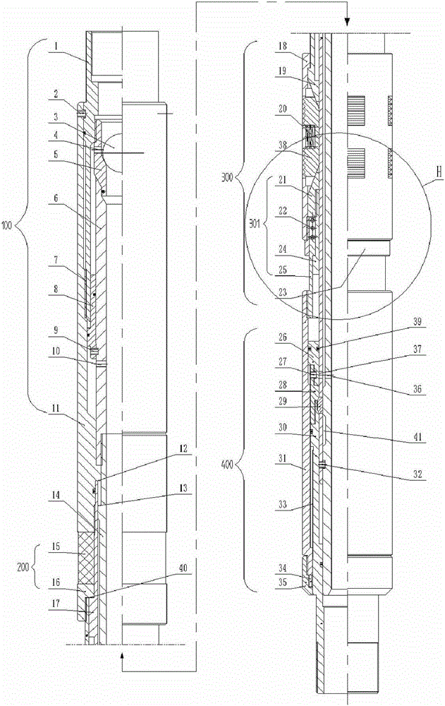
[0052] a. Use tubing or drill pipe to send the hydraulic packer to the downhole design position. The necessary string combination is: tubing or drill pipe + hydraulic packer [without ball (3)] + pressure controller;

[0053] b. Increase the hydraulic pressure in the string to reach the design value of the setting force of the hydraulic packer;

[0054] c. Maintain or reduce the hydraulic pressure in the pipe string, but ensure that the hydraulic pressure in the pipe string is greater than the hydraulic pressure in the oil jacket annulus;

[0055] d. Lower the pipe string from the wellhead to load the hydraulic packer with a mechanical force of 50kN-250kN;

[0056] e. Remove the hydraulic pressure in the string.

[0057] f. Throw the ball (3) from the tubing or drill pipe, and make the ball (3) fall on the ball seat (5);

[0058] g. Increase the hydraulic pressure in th...

Embodiment 2

[0064] The installation method of preferred embodiment 2 hydraulic packer comprises the following steps:

[0065] a. Use tubing or drill pipe to send the hydraulic packer to the downhole design position. The necessary string combination is: tubing or drill pipe + hydraulic packer;

[0066] b. Increase the hydraulic pressure in the string to reach the design value of the setting force of the hydraulic packer;

[0067] c. Maintain or reduce the hydraulic pressure in the pipe string, but ensure that the hydraulic pressure in the pipe string is greater than the hydraulic pressure in the oil jacket annulus;

[0068] d. Lower the pipe string from the wellhead to load the hydraulic packer with a mechanical force of 50kN-250kN;

[0069] e. Remove the hydraulic pressure in the string.

[0070] f. Lift the oil pipe or drill pipe to the original suspension, turn the pipe string to the right to unscrew the hand thread (7);

[0071] g. Lift the tubing or drill pipe out of the upper join...


PUM


Abstract

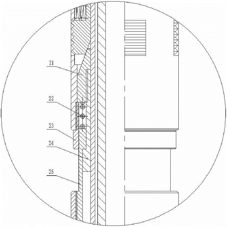
The invention discloses a hydraulic packer and a mounting method of the hydraulic packer. The hydraulic packer and the mounting method of the hydraulic packer are used for downhole oil production by layer and the like. The hydraulic packer comprises a releasing mechanism, a rubber barrel sealing mechanism, an anchoring mechanism, a setting mechanism and the like. The anchoring mechanism comprises an upper cone, a lower cone, a slip, a reset spring and a slip cage, the upper end of a T-shaped sleeve of the lower cone is connected with a conical head, the T-shaped sleeve is sleeved with a compression sleeve, matched steps are arranged between the compression sleeve and the T-shaped sleeve, the compression sleeve can axially slide along the outer side of the T-shaped sleeve, and an expansion spring is arranged between the compression sleeve and the conical head and on the outer periphery of the T-shaped sleeve. The releasing mechanism is arranged on the upper portion of the hydraulic packer and comprises an upper connector, a releasing sleeve, a fishing barrel, a releasing piston, a ball seat, a ball and the like. After setting of the packer is completed, releasing can be achieved by throwing the ball and can be achieved by rotating a pipe column in the forward direction. Due to the fact that the expansion spring is arranged on the lower cone, the conical head can reliably expand the slip due to the thrust of the expansion spring. Meanwhile, due to the design of the releasing mechanism, the problem that the lower tensile force borne by the packer is insufficient is solved.

Description

technical field [0001] The invention relates to the technical field of downhole packers used in oil exploitation, in particular to an downhole packer with hydraulic and mechanical double compression functions and an installation method thereof. Background technique [0002] In well completion and oil production operations in the field of oil exploitation, downhole packers are often used to separate oil layers, seal oil casing annulus, and hang downhole tubing strings. In order to improve the sealing effect of the packer, the Chinese patent application number CN201310333524, the application date is 2013.08.02, and the invention name is "double-acting compression packer and its use method", which discloses a hydraulically set compression rubber cylinder, and then The packer of the two types of rubber cylinder compression through the string pressurization compression rubber cylinder, this packer can indeed improve the sealing performance and validity period of the packer. Howe...

Claims


Application Information

Patent Timeline
Patent Type & Authority Patents(China)
IPC IPC(8): E21B33/126E21B23/06
Inventor 王世杰张瑞霞刘建新王卫明魏伟韩博杨洁
Owner CHINA PETROLEUM & CHEM CORP
Learn More