
Pressure stop valve of hydraulic variable displacement motor

A variable motor and cut-off valve technology, applied in the hydraulic field, can solve the problems of increasing the wear of the valve stem 102, reducing the stability of the pressure cut-off valve 100, and the instability of the valve stem 102

Active Publication Date: 2014-04-16
XUZHOU HEAVY MASCH CO LTD
View PDF5 Cites 0 Cited by
  • Summary
  • Abstract
  • Description
  • Claims
  • Application Information

AI Technical Summary

Problems solved by technology

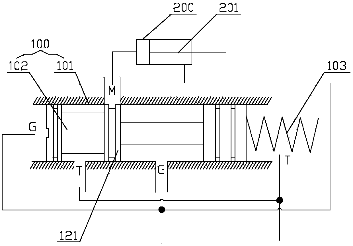
[0011] The action area of ​​the pressure cut-off valve 100 for the reversing pressure is relatively large, which is the left end surface of the valve stem 102, which makes the valve stem 102 unstable during operation and has a large reversing impact; as long as the pressure at the high pressure end of the valve stem 102 fluctuates, the valve stem will 102 responds immediately and moves back and forth, which not only reduces the stability of the pressure cut-off valve 100, easily causes intermittent vibration of the variable motor, but also increases the wear of the valve stem 102, reducing the service life of the pressure cut-off valve 100
[0012] In addition, since the valve port of the pressure cut-off valve 100 is covered by the neutral zero, during the reversing process of the valve stem 102, the pressurization and pressure relief of the working oil port M are faster, especially when the valve stem 102 moves to the left When the working oil port M is connected with the high-pressure port G, because the high-pressure port G is a high-pressure point, the working oil port M is easy to form an instantaneous pressure shock, which makes the pressure in the large chamber of the variable cylinder 200 fluctuate greatly, resulting in the variable piston 201 not moving. smooth

Method used


Image

  • Pressure stop valve of hydraulic variable displacement motor
  • Pressure stop valve of hydraulic variable displacement motor

Examples


Embodiment Construction

[0038] The core of the present invention is to provide a pressure cut-off valve for a hydraulic variable motor. The valve stem of the pressure cut-off valve runs smoothly, has high stability and has a long service life.

[0039] In order to enable those skilled in the art to better understand the solution of the present invention, the present invention will be further described in detail below in conjunction with the accompanying drawings and specific embodiments.

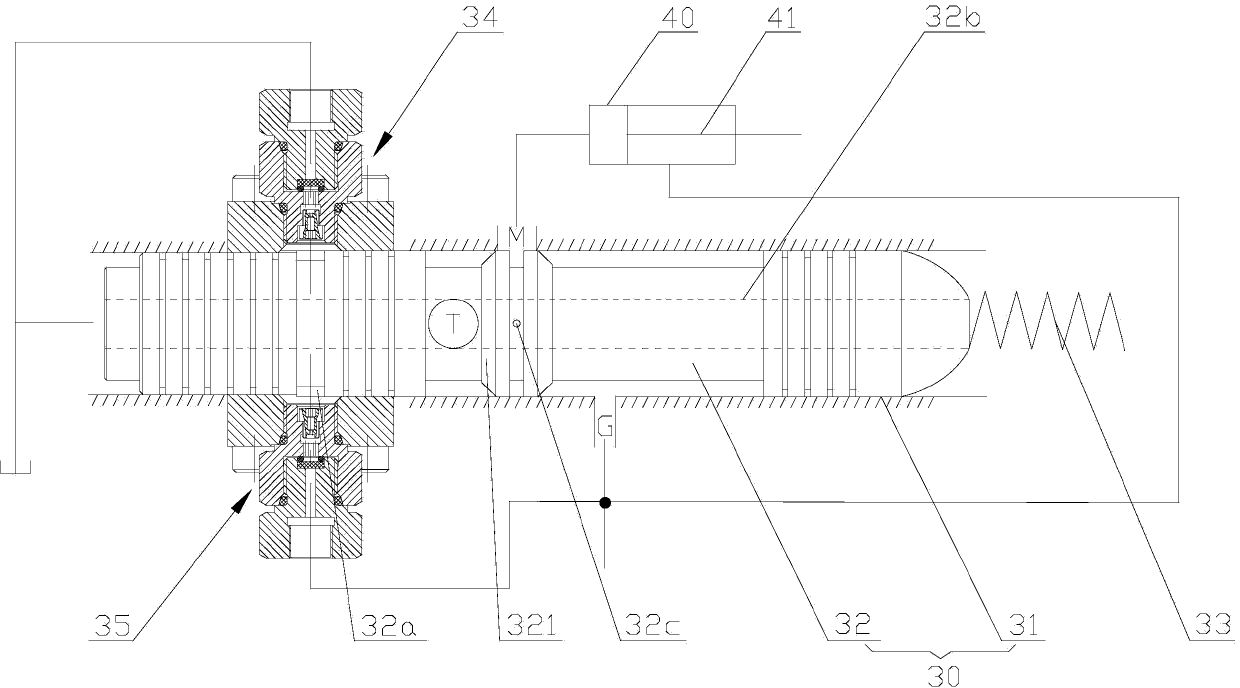
[0040] Please refer to figure 2 , figure 2 It is a structural schematic diagram of a specific embodiment of the pressure cut-off valve provided by the present invention.

[0041] In this embodiment, the pressure cut-off valve 30 of the hydraulic variable motor includes a valve body 31 with a valve cavity and a valve stem 32 inserted in the valve body 31; one end of the valve stem 32 is provided with a reversing spring 32, and communicates with the oil tank ;

[0042] The valve cavity is provided with a working...


PUM


Abstract

The invention discloses a pressure stop valve of a hydraulic variable displacement motor. The pressure stop valve comprises a valve body with a valve cavity and a valve rod inserted to the valve body. One end of the valve rod is provided with a reversing spring and is communicated with an oil tank. The valve cavity is provided with a working oil opening, a high pressure opening and an oil returning opening. The working oil opening is communicated with a large cavity of a variable displacement cylinder of the hydraulic variable displacement motor. The high-pressure opening is communicated with a small cavity of the variable displacement cylinder. The oil returning opening is communicated with the low-pressure end of the valve rod. When the valve rod moves, the communication state of the working oil opening and the oil returning opening or the high-pressure opening is changed, a groove is formed in the other end of the valve rod in the periphery direction, and the groove is communicated with the high-pressure side of the hydraulic variable displacement motor through an inlet damping component and is communicated with the oil tank through a bypass damping component. Accordingly, the action area of valve rod reversing pressure is decreased, reversing impact is lowered, the valve rod can operates stably, and intermittent shaking of the hydraulic variable displacement motor caused by the fact that valve rod response is too sensitive is avoided.

Description

technical field [0001] The invention relates to the field of hydraulic technology, in particular to a pressure cut-off valve of a hydraulic variable motor. Background technique [0002] When the crane is hoisting, the weight of the heavy objects is different each time. It is usually hoped that the heavy objects can be lifted when the heavy objects are heavy. According to the requirements of the working conditions, the hoisting mechanism of the crane is generally driven by a variable motor. [0003] At present, a variable variable motor commonly used in the market is HD1D (hydraulic control, pressure cut-off) variable variable motor. When this variable variable motor is working, the motor displacement changes from large displacement to small displacement, and the working pressure of the motor increases gradually. When the set pressure is reached, the pressure needs to be cut off to increase the displacement of the motor until it matches the working pressure of the system. S...

Claims


Application Information

Patent Timeline
IPC IPC(8): F15B13/02
Inventor 单增海胡小冬焦国旺朱鹏
Owner XUZHOU HEAVY MASCH CO LTD
Learn More