
Valve system

A proportional valve and distribution valve technology, applied in the field of valve systems, can solve the problems of long load adjustment time and inability to accurately locate the load, and achieve the effect of low cost and short adjustment time

Inactive Publication Date: 2014-04-16
ROBERT BOSCH GMBH
View PDF8 Cites 2 Cited by
  • Summary
  • Abstract
  • Description
  • Claims
  • Application Information

AI Technical Summary

Problems solved by technology

[0007] If the distributing valve is designed small, ie has a small flow cross-section, this results in relatively long adjustment times for the load
On the other hand, if the distribution valve is constructed large, it is almost impossible to precisely position the load

Method used


Image

  • Valve system
  • Valve system
  • Valve system

Examples


Embodiment Construction

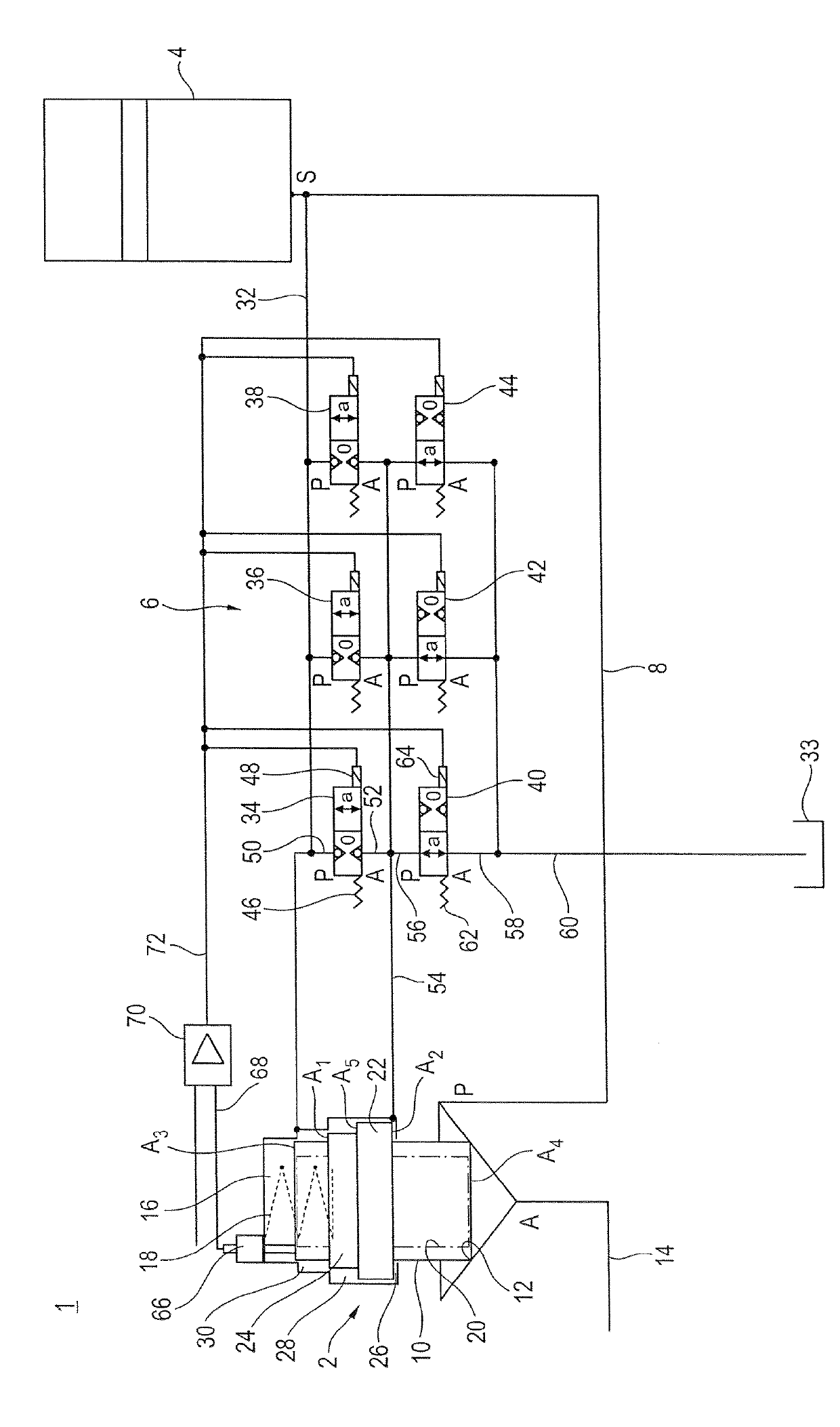
[0088] according to figure 1 A valve system 1 according to the invention is shown. The valve system has a proportional valve 2 for opening and closing a control (zusteuern) pressure medium connection between a hydraulic accumulator 4 and a consumer (not shown). The proportional valve 2 can be controlled here by a pilot control valve line 6 . Such a valve system 1 is used in particular for applications in printing machines, injection molding machines, molding machines or casting machines, since a proportional valve 2 with high dynamics and a high flow rate is required for hydraulic loads.

[0089] The proportional valve 2 basically corresponds to the installation of a continuous valve or an active logic valve, as is shown, for example, in applicant's data sheet RD 21040 / 11.10. However, the proportional valve 2 according to the first embodiment has an additional control surface A 1 and A 2 , which is explained in detail below.

[0090] The proportional valve 2 has a pressur...


PUM


Abstract

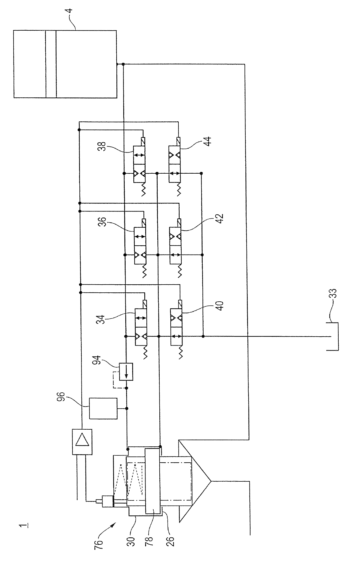
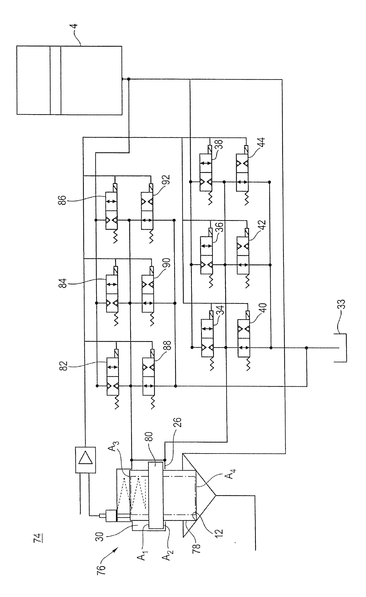
The invention discloses a valve system with a proportional valve, wherein pivot control is performed on the proportional valve through a pivot control valve line. For adjusting a slide valve of the proportional valve in a first direction, the valve system is provided with at least two distribution valves with different rated parameters. For adjusting the slide valve in an opposite direction, at least two distribution valves with different rated parameters are also arranged. Corresponding larger distribution valves are used for quickly adjusting the slide valve and correspondingly realize short adjustment time, and corresponding smaller distribution valves are used for accurately positioning the slide valve.

Description

technical field [0001] The invention relates to a valve system with a hydraulic proportional valve according to the preamble of claim 1 . Background technique [0002] Such a valve system is known from DE 10 2009 030 888 A1. The valve system has, as the main stage, a proportional valve with a multi-stage piston that can open and close the pressure medium connection between the control pressure medium accumulator and the load. The multi-stage piston has a smaller end face and a rear face pointing away from the end face and delimiting a spring chamber. Viewed in the longitudinal direction, an annular surface pointing away from the rear surface is provided on the multistage piston between the rear surface and the front surface. The multi-stage piston is acted upon with a spring force in the direction of the valve seat of the multi-stage piston by means of a valve spring arranged in the spring chamber. The ring surface of the multistage piston can be acted upon by the pressur...

Claims


Application Information

Patent Timeline
Patent Type & Authority Applications(China)
IPC IPC(8): F15B13/043F15B21/08
CPCF15B2211/30575F15B2211/40592F16K31/1225F15B2211/328F16K31/42F15B13/0431F15B2013/0409F15B2211/329F15B2211/355F15B2211/6355F15B2211/67
Inventor H.费斯特林S.施密特H.恩格特
Owner ROBERT BOSCH GMBH
Learn More