Pinion assembling tray and pinion assembling device

A technology for assembling devices and assembling trays, which is applied in the directions of assembling machines, transmission parts, belts/chains/gears, etc., which can solve the problems of cycle shortening, limitation of productivity, time-consuming, etc., so as to reduce the possibility of falling off, The effect of shortening cycle time and increasing productivity

Inactive Publication Date: 2014-04-16
MUSA PRECISION IND CO LTD
View PDF2 Cites 10 Cited by
  • Summary
  • Abstract
  • Description
  • Claims
  • Application Information

AI Technical Summary

Problems solved by technology

For example, during the insertion of the pinion assembly 123, the pressing and riveting of the shaft 108 cannot be performed
Insertion of pinion assembly 123 is not possible during press-fitting of shaft 108 and during riveting
There is a limit in productivity because multiple components cannot be moved simultaneously
[0013] In addition, from other points of view, for example, since the outer diameter of the shaft 108 is inevitably deviated, and the diameter of the hole on the carrier side is inevitably deviated, the positional alignment of the pinion assembly 123 and the shaft 108 Pressing into the carrier 103 takes time, and as a result, there is a limit to shortening the cycle

Method used


Image

  • Pinion assembling tray and pinion assembling device
  • Pinion assembling tray and pinion assembling device
  • Pinion assembling tray and pinion assembling device

Examples


Embodiment Construction

[0058] Hereinafter, embodiments of the present invention will be described based on the drawings. Also, the drawings are viewed from the directions of the reference numerals.

[0059] 【Example】

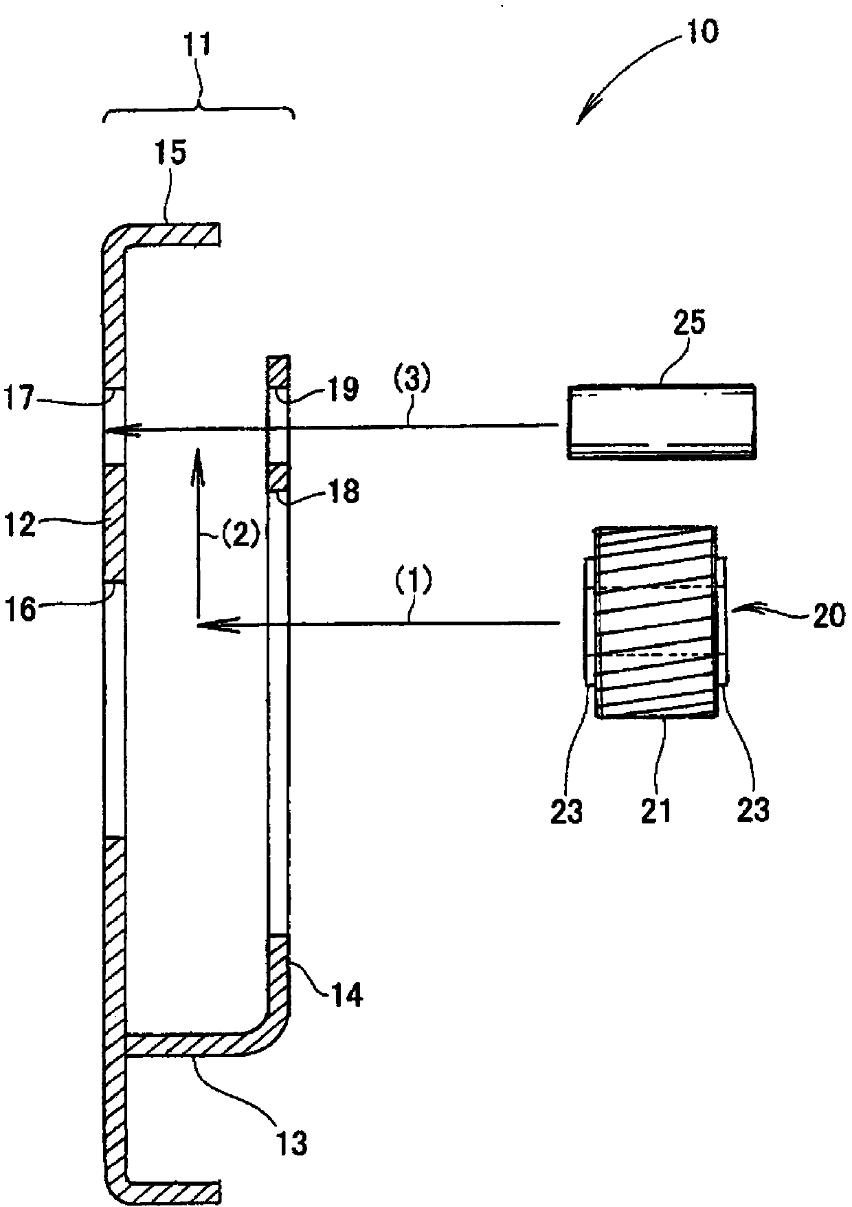
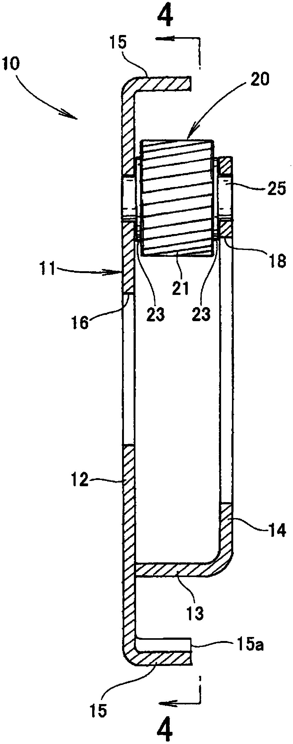
[0060] like figure 1 As shown, the planet carrier assembly 10 is composed of the planet carrier 11 , the pinion assembly 20 and the shaft 25 .

[0061] Further, the carrier 11 is composed of a carrier base 12 extending from the carrier base 12 in the longitudinal direction (including substantially the longitudinal direction) of the shaft 25 , an arm portion 13 , and a circular plate portion 14 . The plate portion 14 extends from the distal end of the arm portion 13 in parallel with the carrier base 12 .

[0062] In this example, the peripheral wall portion 15 stands up from the outer edge of the carrier base 12 toward the disc portion 14 .

[0063] The carrier base 12 is provided with a first center hole 16 and a first shaft insertion hole 17 into which the shaft 25 is inserted. ...


PUM


Abstract

The invention provides a pinion assembling tray and a pinion assembling device, which can assemble a pinion to a planet carrier for operation with high efficiency so as to raise assembling productivity. The pinion assembling device (60) is composed of a conveyor (61) for conveying a pinion assembling tray (30) and a first station (S1), a second station (S2) and a third station (S3) configured along the conveyor (61). At the first station (S1), a pinion module is inserted into the planet carrier and moves, is inserted into a shaft at the second station (S2) and is in pivot joint with the shaft at the third station (S3). The pinion assembling device can independently perform pinion module positioning and shaft inserting, shorten a period and increase productivity.

Description

technical field [0001] The present invention relates to automatic assembly technology of pinions built into a planetary gear mechanism. Background technique [0002] like Figure 19 As shown, the planetary gear mechanism 100 is composed of the following parts: a sun gear 101; a planet carrier 103, which rotatably supports the planet gears 102, 102 surrounding the sun gear 101; and a ring gear 104, which surrounds the planet gears 102, 102 102 and meshes with the planetary gears 102, 102. The planetary gear 102 is also referred to as a pinion, and therefore, the planetary gear will be described later as a pinion. [0003] In this example, planet carrier 103 is restrained by brake member 105 . When the sun gear 101 rotates, the pinion gears 102 and 102 are rotated by the sun gear 101 , and the ring gear 104 is rotated by the pinion gears 102 and 102 . [0004] The carrier 103 is composed of a carrier base 111 , arm portions 112 and 112 extending from the carrier base 111 , ...

Claims


Application Information

Patent Timeline
Patent Type & Authority Applications(China)
IPC IPC(8): F16H57/023B23P21/00
CPCB23P21/00F16H57/023
Inventor 岩波健二
Owner MUSA PRECISION IND CO LTD
Why Eureka
Try Eureka