
Mechanical scanning meter wave radar based method for improving single pulse angle measurement

A single-pulse angle measurement and meter wave radar technology, applied in the radar field, can solve the problems of misalignment of the center beam to the target, low angle measurement accuracy, affecting the radar resolution and detection and tracking target accuracy, etc., so as to improve the signal-to-noise ratio. and angle measurement accuracy, the effect of good robustness

Active Publication Date: 2014-04-16
XIDIAN UNIV
View PDF8 Cites 30 Cited by
  • Summary
  • Abstract
  • Description
  • Claims
  • Application Information

AI Technical Summary

Problems solved by technology

However, affected by the shortcomings of the wide beam of the aircraft-scanning meter-wave radar and the inaccuracy of the center beam on the target, the accuracy of the amplitude-phase and difference beam single-pulse angle measurement method is higher than that of the maximum signal method, but its angle measurement accuracy is greatly affected by noise. The accuracy needs to be further improved, especially in the case of multiple targets within the same beam width, the angle measurement accuracy is still very low, which affects the resolution of the radar and the accuracy of detecting and tracking targets

Method used


Image

  • Mechanical scanning meter wave radar based method for improving single pulse angle measurement
  • Mechanical scanning meter wave radar based method for improving single pulse angle measurement
  • Mechanical scanning meter wave radar based method for improving single pulse angle measurement

Examples


Embodiment Construction

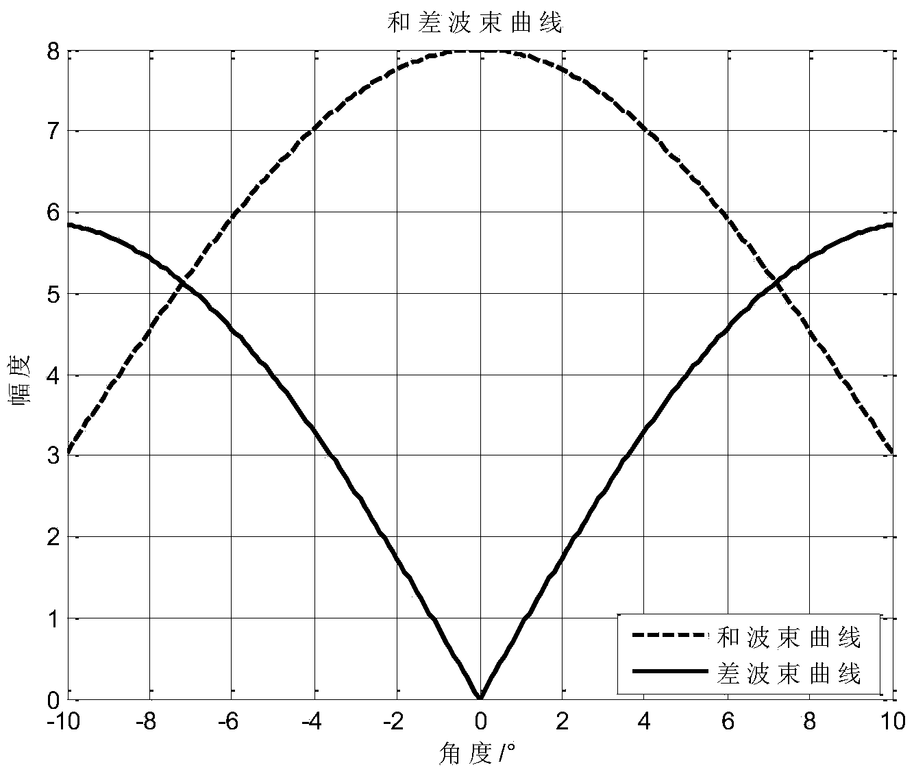
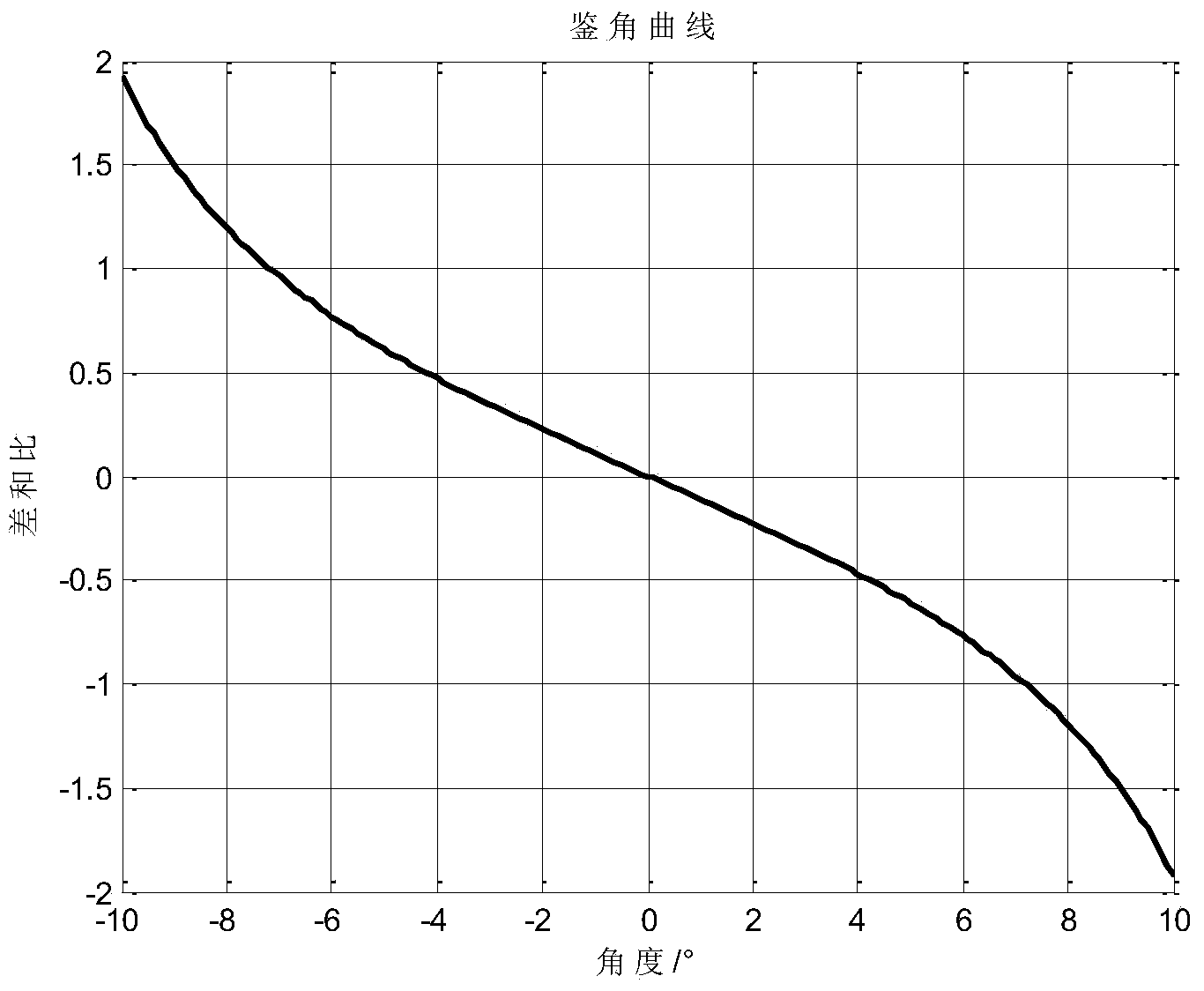
[0034] refer to figure 1 , the specific implementation steps of the present invention are as follows:

[0035] Step 1, the antenna of the machine-scanned radar is equivalent to an array antenna composed of array elements.

[0036] 1a) The antenna of the machine-scanned radar is equivalent to an equidistant linear array composed of N array elements, that is, the array element spacing d between any two adjacent array elements is equal, and it is the wavelength of the signal transmitted by the meter wave radar Half of λ, d=λ / 2;

[0037] 1b) The antenna array is equally divided into left and right sub-arrays, the number of elements in each sub-array is N / 2, and N is an even number greater than or equal to 4.

[0038] Step 2, set the angle detection curve table.

[0039] 2a) Divide the angle measurement range -90°~90° into a wave position at intervals of 10°;

[0040] 2b) For any wave position, the left half array synthesized beam B of the wave position is obtained from the N / 2 a...


PUM


Abstract

The invention discloses a mechanical scanning meter wave radar based angle measurement method which mainly aims at solving the problem that the angle measurement of a mechanical scanning meter wave radar is low in accuracy by the traditional single pulse method. The mechanical scanning meter wave radar based method comprises step 1, dividing an antenna into two sub-matrixes equally and transmitting pulse signals; step 2, performing coherent accumulation on received echo signals and obtaining data after the accumulation; step 3, performing DET (Discrete Fourier Transformation) calculation on the data after the accumulation; step 4, finding out a point in a doppler channel, reserving M points on the left side and the right side of the point and setting rest points to be 0, wherein the point is corresponding to the doppler frequency; step 5, performing IDFT (Inverse Discrete Fourier Transform) calculation on the data which are set to be 0; step 6, obtaining a sum beam and a difference beam according to obtained two groups of data after the IDFT calculation; step 7, performing the sum and difference beam single pulse angle measurement on the sum beam and the difference beam to obtain an off-axis angle of a target; step 8, adding the off-axis angle to a reference angle to obtain the accurate angle of the target. According to the mechanical scanning meter wave radar based method for improving the single pulse angle measurement, the accuracy of the angle measurement is high, a plurality of targets can be distinguished, and the mechanical scanning meter wave radar based method can be applied to the target accurate positioning and multi-target detection of the mechanical scanning meter wave radar.

Description

technical field [0001] The invention belongs to the technical field of radar, and in particular relates to a meter-wave radar angle measurement method, which can be used for single-pulse angle measurement of a target when a single target or multiple targets exist simultaneously in a mechanical scanning radar. Background technique [0002] Due to the small signal attenuation and long detection distance, meter wave radar has unique advantages in over-the-horizon detection and anti-electronic interference. However, due to the long wavelength and wide beam of meter wave radar, its angular resolution is poor. Angle measurement accuracy is low. Mechanical scanning radar has been widely used due to factors such as low cost and simple implementation. The angle measurement method of machine-scanned radar generally adopts the maximum signal method, but the accuracy of this method is poor, especially for machine-scanned meter wave radar. Its electrical size is small, the beam is wide...

Claims


Application Information

Patent Timeline
IPC IPC(8): G01S13/06
CPCG01S7/41G01S13/06
Inventor 赵永波高炎水鹏朗刘宏伟程增飞冯大政
Owner XIDIAN UNIV
Learn More