FIFO cache sharing router based on fiber delay lines and working method thereof

An optical fiber delay line and shared buffer technology, applied in digital transmission systems, electrical components, transmission systems, etc., can solve the problems of energy consumption, limit the speed of optical data packet processing, etc., achieve high resource utilization, avoid extra time The effect of delaying and avoiding port conflicts

Inactive Publication Date: 2014-04-16
NANJING UNIV
View PDF0 Cites 2 Cited by
  • Summary
  • Abstract
  • Description
  • Claims
  • Application Information

AI Technical Summary

Problems solved by technology

However, this "optical-electrical-optical" conversion method severely limits the speed o

Method used


Image

  • FIFO cache sharing router based on fiber delay lines and working method thereof
  • FIFO cache sharing router based on fiber delay lines and working method thereof
  • FIFO cache sharing router based on fiber delay lines and working method thereof

Examples


Embodiment Construction

[0028] The present invention will be further described below in conjunction with accompanying drawing.

[0029] To achieve the purpose of the present invention, the present invention provides an all-optical FIFO shared buffer queue structure based on fiber delay lines, which will be described in detail below with reference to the accompanying drawings.

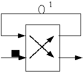
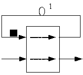
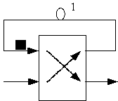
[0030] The optical network lacks the necessary optical cache to realize store-forward optical packet switching. The optical FIFO shared buffer queue structure of the present invention avoids the low-efficiency optical-electrical-optical conversion to realize optical packet storage. The timeline and optical switching matrix implement packet buffering. The optical fiber delay line mainly utilizes the delay characteristic of the optical signal when it propagates in the optical fiber, and uses different lengths of optical fiber as the medium to delay the input optical signal, thereby simulating the optical buffer function. Take t...


PUM


Abstract

The invention discloses a FIFO cache sharing router based on fiber delay lines and a working method of the FIFO cache sharing router. The cache sharing router allows sharing of N packets and structurally comprises a (N+M)*(N+M) non-blocking optical switching matrix, the M fiber delay lines and a logic control unit. By setting optical fiber delay line lengths (img file='23068dest_path_image002.TIF', wi='216', he='24'/) and adopting the packet scheduling algorithm based on sorting, the FIFO light cache sharing function can be simulated under the condition of the arrival of any packet by the FIFO cache sharing router based on the fiber delay lines according to the working method.

Description

technical field [0001] The invention relates to an optical FIFO shared buffer queue, which specifically utilizes an optical fiber delay line to realize optical packet dynamic buffering, realizes optical buffer sharing through a feedback structure, and then uses a sorting-based scheduling strategy to ensure packet FIFO scheduling and fully utilizes optical fiber delay line storage Resource, implements an all-optical FIFO shared buffer queue based on fiber delay line. Background technique [0002] In the optical transmission network, since there is no physical optical memory, at the network nodes that transmit information in a store-and-forward manner, people usually first convert the arriving optical signal into an electrical signal, and then pass it through the electrical memory ( Such as RAM) storage, and then converted into an optical signal and sent to the optical channel when the port is idle. However, this "optical-electrical-optical" conversion method severely limits ...

Claims


Application Information

Patent Timeline
IPC IPC(8): H04L12/771H04L12/863H04L45/60
Inventor 王晓亮谢安姜晓鸿陆桑璐
Owner NANJING UNIV
Why Eureka
Try Eureka