air conditioner

A technology of air conditioning and control device, which is applied in the directions of space heating and ventilation, heating mode, lighting and heating equipment, etc. It can solve the problem of difficulty in setting the circulation volume of the refrigerant side, so as to prevent the occurrence of start-stop losses and suppress the The effect of preventing excessive rise in blowing temperature

Active Publication Date: 2015-11-25
MITSUBISHI ELECTRIC CORP
View PDF12 Cites 0 Cited by
  • Summary
  • Abstract
  • Description
  • Claims
  • Application Information

AI Technical Summary

Problems solved by technology

Therefore, also in the air-conditioning apparatus described in Patent Document 2, there is a problem similar to that of Patent Document 1.
[0011] In addition, in the air-conditioning apparatus described in Patent Document 2, the circulation amount on the refrigerant side is controlled so that the heat medium flowing out of the heat exchanger related to heat medium becomes the first target temperature. In the case where multiple heat exchangers related to heat medium that simultaneously perform the same function as condensers or evaporators are connected, since the air-conditioning load borne by each heat exchanger related to heat medium is different, the set refrigerant side circulation amount changes. very difficult

Method used


Image

  • air conditioner
  • air conditioner
  • air conditioner

Examples


Embodiment approach

[0025] Hereinafter, the air-conditioning apparatus of this embodiment is demonstrated. In addition, in the following description, when it is necessary to describe the same structure differently, etc., the letter is added to the end of the code|symbol and described.

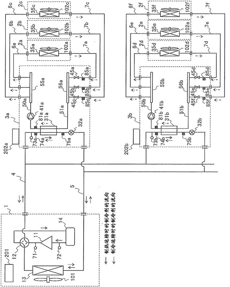
[0026] figure 1 It is a system circuit diagram of the air-conditioning apparatus which concerns on embodiment of this invention. In the air conditioner of this embodiment, the compressor 11, the four-way valve 12 that is the refrigerant flow switching device, the heat source side heat exchanger 13, the accumulator 14, the heat exchanger 31 related to heat medium, and the electronic expansion valve are connected by piping. Such as expansion device 32 to constitute a refrigeration cycle.

[0027] More specifically, the compressor 11 pressurizes and discharges (sends out) the sucked refrigerant. The four-way valve 12 connects the flow path of the refrigerant discharged from the compressor 11 to the heat source sid...


PUM


Abstract

Disclosed is an air-conditioning apparatus that includes a plurality of intermediate heat exchangers performing the same function (as a condenser or an evaporator) and allows each intermediate heat exchanger 31 to exchange heat between a refrigerant heated or cooled in a refrigeration cycle on a heat source side and a heat medium flowing through a heat medium circuit on a use side such that heat energy produced on the heat source side is transmitted to use side heat exchangers 35. A controller 202 calculates the difference between a heat medium inlet temperature Twi and a heat medium outlet temperature Two of the use side heat exchanger 35 which is operating to obtain a heat medium temperature difference ”Tw for the use side heat exchanger 35, and controls a heat medium flow control device 45 such that the heat medium temperature difference ”Tw reaches a target heat medium temperature difference ”Twm. When the heat medium inlet temperature Twi deviates from a predetermined range, the controller 202 changes the target heat medium temperature difference ”Twm and controls the heat medium flow control device 45 for at least one of the use side heat exchangers 35 in operation.

Description

technical field [0001] The present invention relates to, for example, an air conditioning device used in a multi-type air conditioner for a building. Background technique [0002] In conventional air-conditioning equipment used in multi-type air conditioners for buildings, etc., heat is exchanged in heat exchangers related to heat medium between the refrigerant heated or cooled on the heat source side and the heat medium flowing in the circuit on the utilization side , transfer the thermal energy generated on the heat source side to the heat exchanger on the utilization side (that is, the indoor unit) (for example, refer to Patent Document 1). The air-conditioning apparatus described in Patent Document 1 detects the temperature difference between the heat medium flowing out and flowing into the use-side heat exchanger (hereinafter referred to as the temperature difference between the inlet and outlet of the indoor unit). Moreover, if the temperature difference between the i...

Claims


Application Information

Patent Timeline
Patent Type & Authority Patents(China)
IPC IPC(8): F25B1/00F24F11/02
CPCF25B30/02F25B13/00F25B25/005F25B2313/0231F25B2313/0232F25B49/00F25B49/02
Inventor 高山启辅东幸志本村祐治
Owner MITSUBISHI ELECTRIC CORP
Why Eureka
Try Eureka