Supercharge Your Innovation With Domain-Expert AI Agents!

Transverse shearing production line

A production line and cross-cutting technology, which is applied in the direction of shearing devices, shearing machine equipment, shearing machine accessories, etc., to achieve the effect of enriching shearing functions and improving production efficiency

Active Publication Date: 2014-04-23
东莞市森永机械有限公司
View PDF10 Cites 8 Cited by
  • Summary
  • Abstract
  • Description
  • Claims
  • Application Information

AI Technical Summary

Problems solved by technology

[0003] With the advancement of technology, the parallelogram or trapezoidal steel sheet cannot meet the requirements, and the side of the steel sheet also needs to be processed. There is a cross-cutting production line on the market, which adds a single-sided scissors to process the side of the steel sheet. , such as cutting rectangular grooves, trapezoidal grooves or V-shaped grooves on the side, etc.

Method used


Image

  • Transverse shearing production line
  • Transverse shearing production line
  • Transverse shearing production line

Examples


Embodiment 1

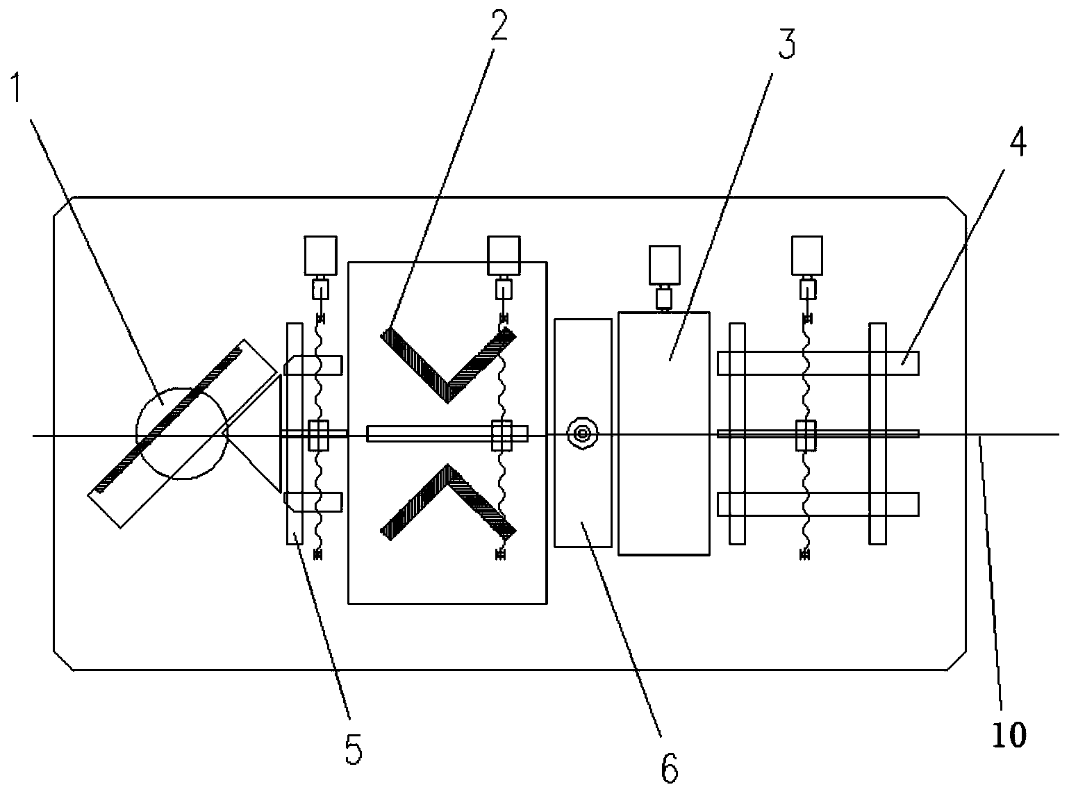
[0027] Embodiment one, such as figure 1 As shown, the cross-cutting production line includes a swinging scissors mechanism 1, a side scissors mechanism 2, a feeding mechanism 3, a front center positioning mechanism 4, a rear center positioning mechanism 5, a punching mechanism 6, a first machine platen 8 and a second machine platen 7. The side scissor mechanism 2 is set on the first machine plate 8, the swing scissor mechanism 1 is set on the second machine plate 7, and the side scissor mechanism 2 is set on the feeding mechanism 3 and the swing scissor mechanism 1 Between, the rear center positioning mechanism 5 is arranged between the side scissors mechanism 2 and the swinging scissors mechanism 1, and the punching mechanism 6 is arranged between the feeding mechanism 3 and the side scissors mechanism 2, and the feeding mechanism 3 is arranged on Between the front center positioning mechanism 4 and the feeding mechanism 3, the punching mechanism 6 is used to punch holes in t...

Embodiment 2

[0034] Embodiment 2, the difference between embodiment 2 and embodiment 1 is that the sliding drive assembly is set as the first air cylinder or the first hydraulic cylinder, and one end of the connecting piece is arranged on the output end of the first air cylinder or the first hydraulic cylinder, The first air cylinder or the first hydraulic cylinder drives the bottom plate to slide through the connecting piece.

[0035] The shear driving assembly is set as a second air cylinder or a second hydraulic cylinder, the output end of the second air cylinder or the second hydraulic cylinder is connected with the swing upper scissors seat, and the second air cylinder or the second hydraulic cylinder drives the swing upper scissors seat to move up and down .

[0036] The left drive component is a left drive cylinder or a left drive hydraulic cylinder, the output end of the left drive cylinder or left drive hydraulic cylinder is connected with the left upper tool seat, and the left dr...


PUM


Abstract

The invention discloses a transverse shearing production line which comprises a feeding mechanism, a lateral shear mechanism and a swing shear mechanism, wherein the side shear mechanism comprises a bottom plate, a left side shear and a right side shear; the left side shear and the right side shear are arranged on the left side and the right side of the bottom plate respectively; the left side shear comprises a left mounting plate, a left guide post, an upper left shear holder, a lower left shear holder and a left driving component; the left guide post is arranged between the left mounting plate and the bottom plate; the left driving component is arranged on the left mounting plate; the left guide post is sleeved with the upper left shear holder; the lower left shear holder is arranged on the bottom plate; the right side shear comprises a right mounting plate, a right guide post, an upper right shear holder, a lower right shear holder and a right driving component; the right guide post is arranged between the right mounting plate and the bottom plate; the right driving component is arranged on the right mounting plate; the right guide post is sleeved with the upper right shear holder; and the lower right shear holder is arranged on the bottom plate. The left side and the right side of a steel sheet are machined respectively by the left side shear and the right side shear, so that a shearing function is greatly enriched, and the production efficiency is improved.

Description

technical field [0001] The invention relates to a cross-cutting production line, in particular to a cross-cutting production line for cutting hard materials such as steel sheets. Background technique [0002] Steel is widely used. For example, silicon steel sheet is a ferrosilicon soft magnetic alloy with extremely low carbon content. Generally, the silicon content is 0.5-4.5%. It is mainly used to make iron cores for various transformers, motors and generators. The cross shear machine is one of the important equipments for processing silicon steel sheets. The Chinese patent application document CN102886557A discloses a cross shear machine. When the servo motor and the reducer rotate to work, the fixed plate and the cutter on the support plate are driven to rotate to process the Silicon steel sheets with special angle requirements such as parallelogram or trapezoid. [0003] With the advancement of technology, the parallelogram or trapezoidal steel sheet cannot meet the req...

Claims


Application Information

Patent Timeline
IPC IPC(8): B23D31/00B23D33/00B23D33/02B21D43/28
Inventor 张永良
Owner 东莞市森永机械有限公司
Features
  • R&D
  • Intellectual Property
  • Life Sciences
  • Materials
  • Tech Scout
  • Unparalleled Data Quality
  • Higher Quality Content
  • 60% Fewer Hallucinations
Learn More