Pressure-controlling limiting type anti-loosing fixture

A restrictive, anti-loosening technology, applied in the direction of manufacturing tools, clamping, clamping devices, etc., can solve the problems of difficult control of clamping force, easy loosening, unreliable clamping, etc., to achieve simple structure and eliminate radial force , the effect of improving work efficiency

Inactive Publication Date: 2014-04-23
WUHU TIANXIONG NEW MATERIAL TECH
View PDF5 Cites 1 Cited by
  • Summary
  • Abstract
  • Description
  • Claims
  • Application Information

AI Technical Summary

Problems solved by technology

[0003] Aiming at the problems of unreliable clamping, uncontrollable clamping force and easy loosening caused by existing clamps, the present invention provides a pressure-controllable restrictive anti-loosening clamp

Method used


Image

  • Pressure-controlling limiting type anti-loosing fixture
  • Pressure-controlling limiting type anti-loosing fixture

Examples


Embodiment 1

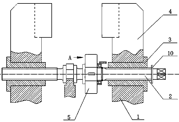
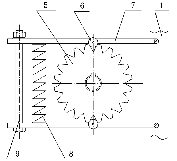
[0019] Such as figure 1 , figure 2 As shown, the pressure-controllable restrictive anti-loosening fixture includes a fixture seat 1, a screw rod 2, a moving block 3, and a clamping block 4. On the concave edge of the upper end of the moving block 3, the screw rod 2 is engaged with the moving block 3, and also includes a ratchet 5, a roller 6, a lever 7, a spring 8, a bolt 9, and a dial 10. The ratchet 5 is assembled on the screw rod through a key. 2, the number of the lever 7 is 2, which are respectively arranged on both sides of the ratchet 5, and are all hinged on the clamp seat 1, and an optical hole is set at the end of the lever 7 away from the clamp seat 1, and the described roller 6 Connected to the lever 7 through a hinge, the two ends of the spring 8 are connected to the lever 7 on both sides of the ratchet 5, the bolt 9 passes through the light hole reserved by the lever 7, and the dial 10 is fixed on on screw 2.

[0020] The spring 8 is a compression spring with...


PUM


Abstract

The invention discloses a pressure-controlling limiting type anti-loosing fixture, and belongs to the field of fixtures. The pressure-controlling limiting type anti-loosing fixture comprises a fixture base, a screw rod, a moving block, a clamping block, wherein the screw rod is meshed with the moving block, a ratchet, a roller, levers, a spring, bolts and a dial. The ratchet is assembled on the screw rod through a key, both ends of the spring are connected with the levers on both sides of the ratchet, the bolt penetrates through a reserved unthreaded hole of each levers, the dial is fixed to the screw rod. The pressure-controlling limiting type anti-loosing fixture solves the problems that in an existing fixture, the fixture is not reliably clamped, clamping force is not easy to control, looseness is prone to occurring are solved, and has the advantages of being simple in structure, reasonable in design and easy to manufacture.

Description

technical field [0001] The invention belongs to the field of fixtures, and more specifically relates to a pressure-controllable restrictive anti-loosening fixture for preventing workpiece clamping from loosening. Background technique [0002] In the machinery manufacturing industry, lathes are widely used to process various parts. When processing parts, the problem of clamping and positioning is involved. When the workpiece is being processed, it is clamped by the fixture so that it can be adapted to various cutting processes. However, due to the vibration of the machine tool and the action of the cutting force during the processing, the fixture is loose, and the workpiece is loose due to insufficient clamping force of the workpiece, which reduces the machining accuracy, and in severe cases, the workpiece will be thrown out. . At the same time, it is necessary to ensure that the clamping force of the fixture is easy to control when clamping the workpiece. Contents of the...

Claims


Application Information

Patent Timeline
Patent Type & Authority Applications(China)
IPC IPC(8): B23Q3/00
CPCB23Q3/06B23Q17/005B23Q2703/02
Inventor 黄雄关
Owner WUHU TIANXIONG NEW MATERIAL TECH
Why Eureka
Try Eureka