
Product multi-end clamping and conveying device

A clamping and conveying, multi-terminal technology, applied in conveyors, mechanical conveyors, transportation and packaging, etc., can solve the problems of small application range, poor clamping stability, and easy to clamp damaged products, so as to improve safety and reliability, avoid The effect of clamping damage and high clamping synchronization

Inactive Publication Date: 2014-04-23
KUNSHAN FOR EASIER AUTOMATION TECH
View PDF0 Cites 2 Cited by
  • Summary
  • Abstract
  • Description
  • Claims
  • Application Information

AI Technical Summary

Problems solved by technology

[0002] The current product clamping and conveying device, because there is only one clamping point, cannot clamp long products, the clamping stability is poor, and the scope of application is small
At the same time, it cannot run quickly after the clamping is completed, and there are many connecting wires on the clamping and conveying device, and the connecting wires are exposed. During the movement, it is easy to be knotted and damaged.
Moreover, the current clamping device controls two independent jaws to perform clamping work through two driving mechanisms. The clamping mechanism is complicated, and the clamping synchronization is poor, so it cannot be effectively coordinated.
At the same time, there is no buffer mechanism at the clamping end of the jaws, and the jaws are very easy to clamp the product, causing unnecessary damage and bringing greater losses to the enterprise.

Method used


Image

  • Product multi-end clamping and conveying device
  • Product multi-end clamping and conveying device
  • Product multi-end clamping and conveying device

Examples


Embodiment Construction

[0016] The present invention will be further described below in conjunction with the accompanying drawings.

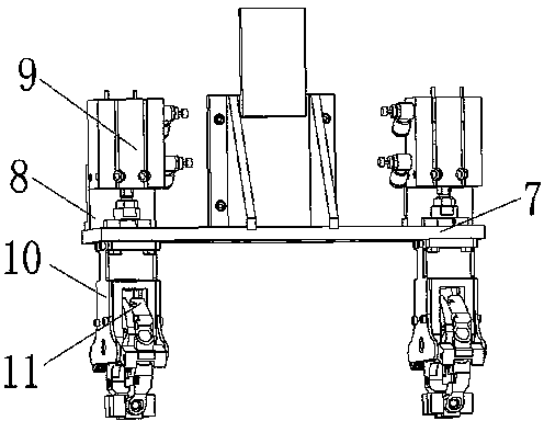
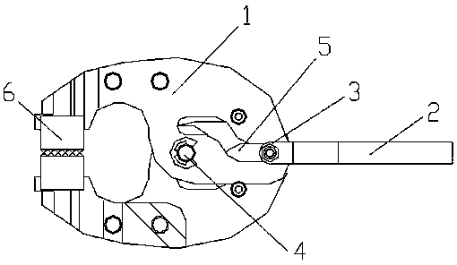
[0017] Such as Figure 1-3 As shown, a product multi-terminal clamping and conveying device includes a strip-shaped fixed plate 12, a slide cylinder 13, a multi-terminal clamping mechanism 14 and a cable protection chain 16, and the multi-terminal clamping mechanism 14 includes a moving plate 15, a supporting plate 7. Two rear plates 8, two cylinders 9, two single clamping mechanisms 11 and four side plates 10, a sliding table cylinder 13 is arranged on the front surface of the elongated fixed plate 12, and the middle part above the support plate 7 There is a moving plate 15, the moving plate 15 is connected with the sliding portion of the slide cylinder 13, a rear plate 8 is respectively arranged on the top position of the supporting plate 7 on both sides of the moving plate 15, and a rear plate 8 is arranged on the front surface of the rear plate 8. There is a cylin...


PUM


Abstract

The invention discloses a product multi-end clamping and conveying device. The product multi-end clamping and conveying device comprises a long-strip-shaped fixing plate and a sliding table air cylinder and is characterized by also comprising a multi-end clamping mechanism; the sliding table air cylinder is arranged on the front surface of the long-strip-shaped fixing plate; a moving plate is arranged on the middle portion above a supporting plate; the moving plate is connected with a sliding portion of the sliding table air cylinder; an air cylinder is arranged on the front surface of a rear plate; two lateral plates are connected to every end at the bottom of the supporting plate; a single clamping mechanism is arranged between the two lateral plates; middle portions of two clamping jaws are flexibly fixed between the two lateral plates through a rotary shaft; two arc-shaped openings are symmetrically formed in the two clamping jaws; an air cylinder rod of the air cylinder penetrates the supporting plate to be connected with the rear end of a connecting rod; a cam is fixed at the front end of the connecting rod; the cam can move along the two arc-shaped openings. The product multi-end clamping and conveying device has the advantages of being simple in structure, convenient to use, flexible in moving, good in clamping synchronicity and safe and reliable in clamping, enabling a connecting line to be protected and having a plurality of clamping stations.

Description

technical field [0001] The invention relates to a clamping and conveying device, in particular to a product multi-end clamping and conveying device. Background technique [0002] Since the current product clamping and conveying device has only one clamping point, it cannot clamp long products, the clamping stability is poor, and the scope of application is small. At the same time, after the clamping is completed, it cannot be operated quickly, and there are many connecting wires on the clamping and conveying device, and the connecting wires are exposed. During the movement, they are easy to be knotted and damaged. Moreover, the current clamping device controls two independent clamping jaws to perform clamping work through two driving mechanisms. The clamping mechanism is complicated, and the clamping synchronization is poor, so it cannot be effectively matched. At the same time, there is no buffer mechanism at the clamping end of the jaws, and the jaws are very easy to pinc...

Claims


Application Information

Patent Timeline
Patent Type & Authority Applications(China)
IPC IPC(8): B65G35/00
Inventor 郭池洪操林曹洪胜
Owner KUNSHAN FOR EASIER AUTOMATION TECH
Learn More