Helical feeding mechanism

A technology of screw feeding and screw conveyor, applied in the field of screw feeding mechanism, can solve the problems of uncontrollable feeding speed, excessive feeding, loss and waste of raw materials, etc., and achieve the effect of expanding the combustion contact area, improving combustion efficiency and saving fuel

Inactive Publication Date: 2014-04-23
浙江华顺炉业有限公司
View PDF7 Cites 5 Cited by
  • Summary
  • Abstract
  • Description
  • Claims
  • Application Information

AI Technical Summary

Problems solved by technology

[0002] In the past, although the feeding device was driven by a motor, it could not be fed manually, but the feeding speed could not be controlled according to the actual amount of material used, resulting in excessive feeding and loss of raw materials.

Method used


Image

  • Helical feeding mechanism
  • Helical feeding mechanism

Examples


Embodiment

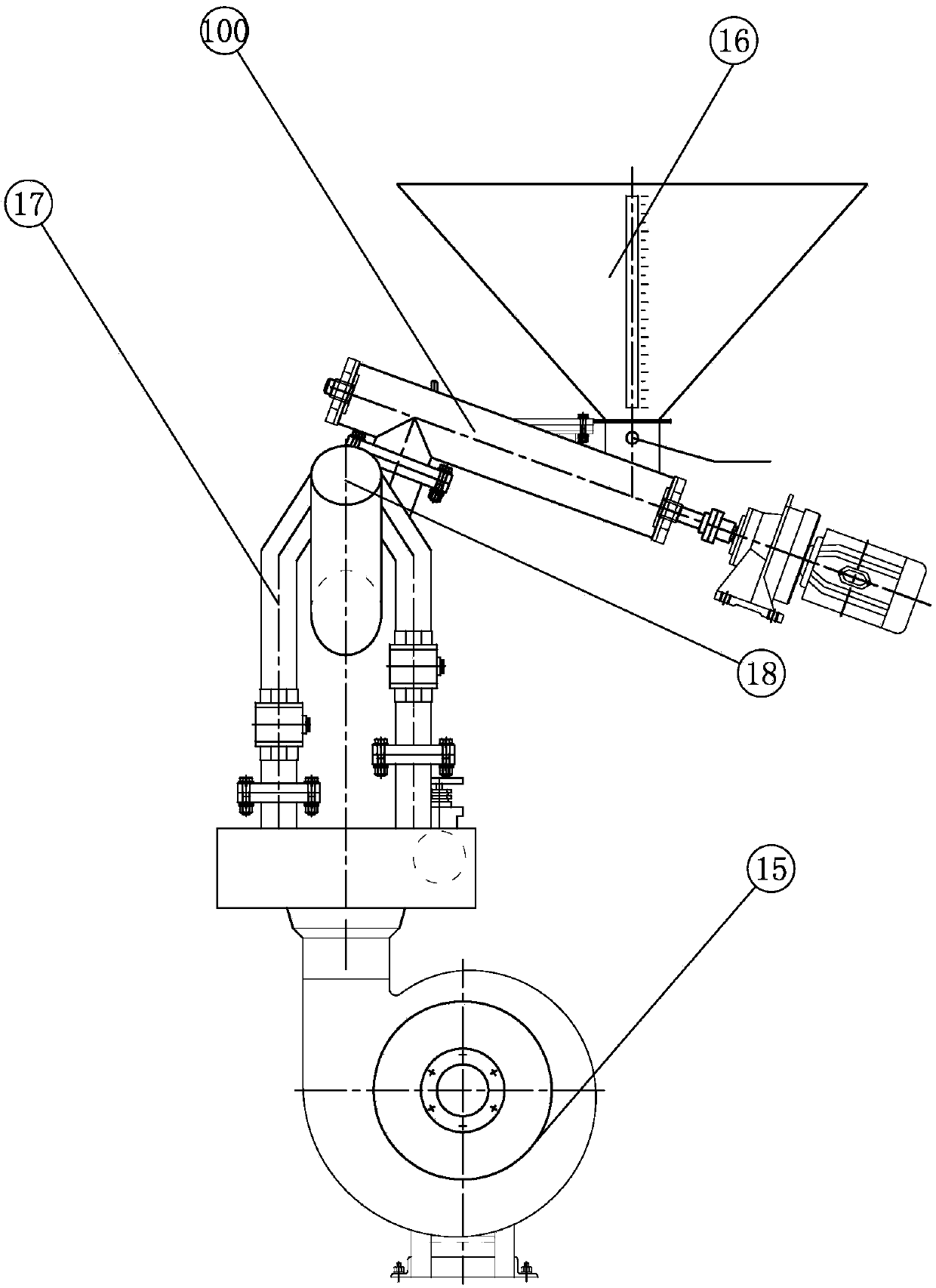
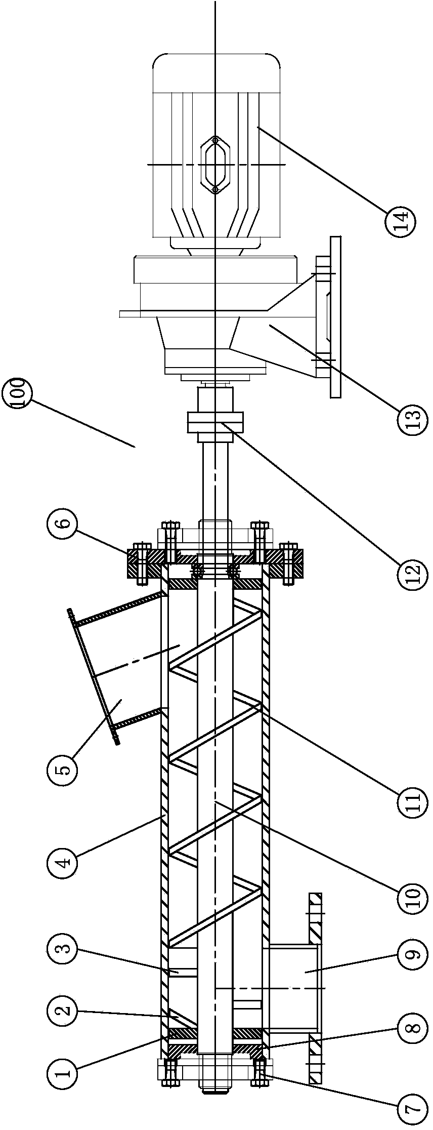
[0015] Embodiment: First, put the material into the feeding device 16, the material enters the barrel 4 through the feed port 5, starts the motor 14, and after being decelerated by the cycloidal pin wheel reducer 13, the power of the motor 14 passes through the shaft coupling 12 It is transmitted to the feeding shaft 10. With the rotation of the feeding shaft 10, the rotation of the screw blade 11 is driven, and the material is sent to the upper end of the barrel 4. After the material is crushed by the crushing knife 3, it is blocked at the baffle plate 1, and then passed through The blanking port 9 is blown into the discharge port 18 through the air flow of the air supply pipe 17, and enters the next link for utilization. There are two air supply pipes 17, which can be opened and closed according to the material demand, and controlled by adjusting the gear position of the fan 15. The air volume can be controlled to achieve the purpose of controlling the air volume.


PUM


Abstract

The invention discloses a helical feeding mechanism. The helical feeding mechanism comprises a helical feeding machine and a fan, wherein the fan is provided with two blast pipes which are connected with the discharging hole of the helical feeding machine; the air outlets of the two blast pipes are arranged on the outer peripheral side of the discharging hole at an interval of 180 degrees. Compared with the conventional feeding device, the helical feeding mechanism has the advantages that the fan is combined with a helical feeding portion, thereby allowing the feeding amount to be controlled in production at any time according to practical requirements by controlling the supply air rate of the fan; moreover, since helical blades and a smashing tool are arranged inside the helical feeding portion, materials can be conveyed and smashed, air blowing is facilitated, the combustion contact area is enlarged indirectly if the conveyed materials are taken as fuel, the combustion efficiency is increased, and the fuel is saved under the condition of supplying equal heat; furthermore, the oxygen feeding amount can be adjusted in a combustion process by controlling the supply air rate, multiple purposes are achieved at one time, and the helical feeding mechanism is environment-friendly and efficient.

Description

technical field [0001] The invention relates to a feeding device, specifically a screw feeding mechanism. Background technique [0002] In the past, although the feeding device was driven by a motor, it could not be fed manually, but the feeding speed could not be controlled according to the actual amount of material used, resulting in excessive feeding and waste of raw materials. Contents of the invention [0003] The technical problem to be solved by the present invention is to provide a screw feeding mechanism that can control the feeding amount according to the material demand. [0004] The technical scheme of the present invention is: a screw feeding mechanism, including a screw conveyor, and a fan, the fan is provided with an air supply pipe connected to the discharge port of the screw feeder, and the air supply pipe is provided with Two, the air outlets of the two air supply pipes are arranged at intervals of 180 degrees on the outer peripheral side of the outlet. ...

Claims


Application Information

Patent Timeline
Patent Type & Authority Applications(China)
IPC IPC(8): B65G65/46B65G69/14B65G53/04
Inventor 潘九林潘卫乔靳宏雷
Owner 浙江华顺炉业有限公司
Why Eureka
Try Eureka