Purlin clip for blown-in insulated ceilings

a technology of insulated ceilings and purlins, which is applied in the direction of ceilings, roofing, covering/linings, etc., can solve the problems of reducing the r-value, reducing the efficiency and effectiveness of controlling temperature in such metal buildings, and reducing the heating and cooling costs. , to achieve the effect of reducing or eliminating thermal conductivity or shorting, and reducing the risk of blown

Active Publication Date: 2013-02-05
HIGH R
View PDF14 Cites 4 Cited by
  • Summary
  • Abstract
  • Description
  • Claims
  • Application Information

AI Technical Summary

Benefits of technology

[0011]The improved purlin clip of the present invention includes a lower leg and an upper arm defining a channel to receive the horizontal leg of a roof purlin. An integral pin is stamped or formed from the lower leg of the clip, and extends downwardly, such that the clip body and pin have a one-piece construction. The pin includes barbs or teeth and a pointed tip. The pin is adapted to pierce a fabric ceiling membrane, such as vinyl or plastic. A cap is press-fit onto the pin so as to be frictionally retained by the barbs, and so as to support and retain the ceiling membrane on the clip. The cap encloses the pin to minimize or eliminate thermal conductivity or shorting, as well as frost or condensation accumulation on the pin. After the ceiling membrane is secured to a plurality of clips across the ceiling, insulation can be easily blown in between the membrane and the roof deck.

Problems solved by technology

However, metal components of these buildings have high thermal conductivity, and thus it is difficult to efficiently and effectively control temperatures within such metal buildings.
Heating and cooling costs can be relatively high.
The roof deck squeezes the insulation above each purlin thereby reducing the R-value and increasing energy loss.
The insulation is installed from the outside of the building, and involves relatively costly labor which can also be dangerous and difficult in windy or wet conditions.
This method of attaching the insulation board to the purlin is time consuming and therefore costly.
Also, the metal screws provide thermal conductivity through the metal purlins and metal roof decking, thereby reducing the R-value and increasing energy costs.
This prior art system works fine for rigid ceiling panels, but will not accommodate light weight ceiling fabric, such as plastic or vinyl, which may be used to support blown-in insulation.

Method used


Image

  • Purlin clip for blown-in insulated ceilings
  • Purlin clip for blown-in insulated ceilings
  • Purlin clip for blown-in insulated ceilings

Examples


Embodiment Construction

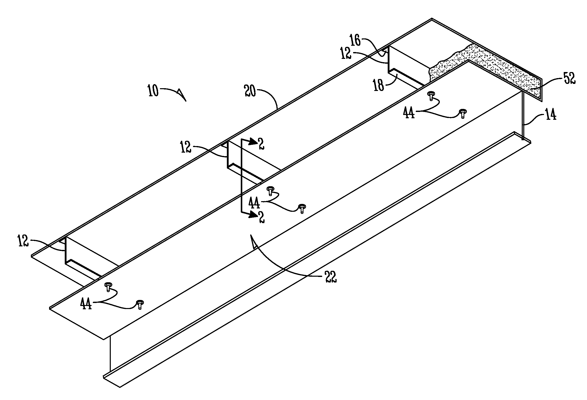
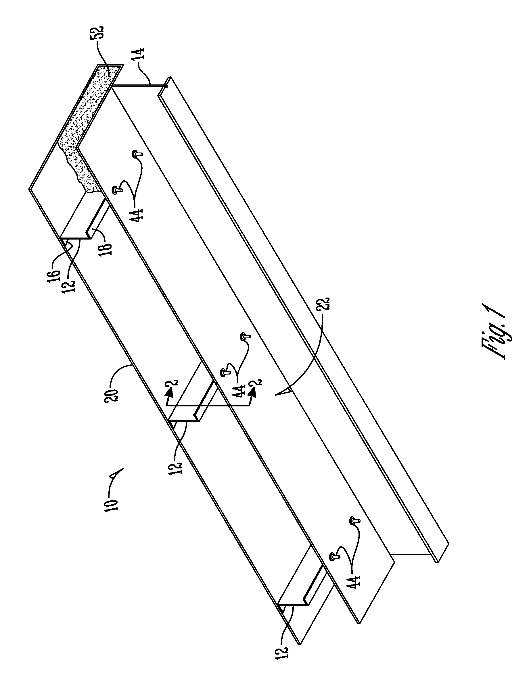
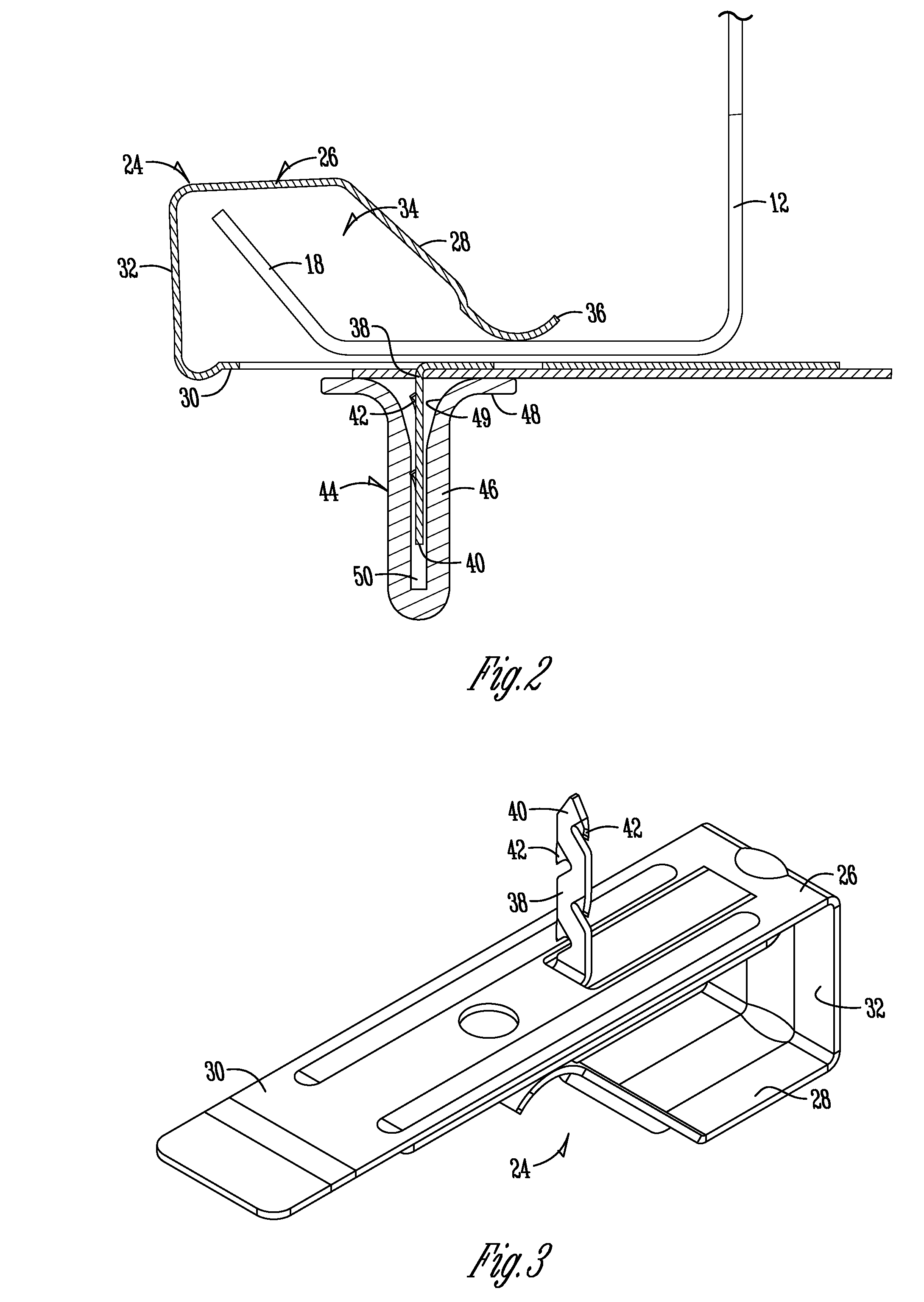
[0021]In FIG. 1, reference numeral 10 generally designates the insulated roof and ceiling structure of a metal building. The ceiling 10 includes a plurality of spaced apart framing members 12, commonly known as purlins, supported on I-beams or other structural framing 14. The purlins 12 are spaced apart and parallel to one another and generally have a Z-profile, as seen in FIG. 1, or a C-profile. Each purlin 12 includes an upper flange 16 and a lower flange 18. A roof deck 20 is attached to the upper flange 16 of the purlins 12 using conventional fasteners (not shown). The deck 20 may be flat or corrugated metal. The purlins 12, I-beams 14, and roof deck 20 are conventionally constructed. The lower ceiling is a fabric sheet or membrane 22. The membrane 22 is secured to the lower flange 18 of the purlins 12 using a plurality of the improved purlin clips 24 of the present invention. In the industry, the ceiling membrane is known as a scrim, and is preferably a tear-resistant material....


PUM


Abstract

An improved purlin clip has an arm and a leg defining a channel to receive the lower flange of a ceiling purlin. A pin is integrally formed with the lower leg of the clip and extends downwardly. The pin is adapted to penetrate a ceiling membrane. A cap is frictionally fit onto the pin to retain the membrane adjacent the purlin, and to support the membrane, with the insulation blown in between the membrane and the ceiling deck. The pin includes teeth or barbs for retentively engaging the cap.

Description

BACKGROUND OF THE INVENTION[0001]Metal buildings are popular due to the relatively quick construction and low cost, as well as low maintenance. However, metal components of these buildings have high thermal conductivity, and thus it is difficult to efficiently and effectively control temperatures within such metal buildings. Heating and cooling costs can be relatively high.[0002]Conventional ceiling insulation in metal buildings involves placing a layer of insulating material over the top of the roof purlins, with the roof deck then being attached over the insulation to the purlins. The roof deck squeezes the insulation above each purlin thereby reducing the R-value and increasing energy loss. The insulation is installed from the outside of the building, and involves relatively costly labor which can also be dangerous and difficult in windy or wet conditions.[0003]Applicant's patent U.S. Pat. No. 6,330,779 overcame many of the problems associated with conventional insulated ceilings...

Claims


Application Information

Patent Timeline
Patent Type & Authority Patents(United States)
IPC IPC(8): E04B9/00E04B1/38E04B5/00E04B1/74
CPCE04D13/1625E04D13/1668
Inventor KINZLER, KEVIN W.
Owner HIGH R
Why Eureka
Try Eureka