
Wire feeding mechanism capable of prolonging wire feeding travel

A wire feeding and stroke technology, applied in the field of wire feeding mechanism that can extend the wire feeding stroke, can solve the problems such as the inability to send the wire to the tool holder, the short wire feeding stroke, the short wire feeding distance of the wire feeding mechanism, etc. Occupied space, smooth wire feeding, and effect of reducing production cost

Active Publication Date: 2014-04-23
烟台力量知识产权服务有限公司
View PDF5 Cites 3 Cited by
  • Summary
  • Abstract
  • Description
  • Claims
  • Application Information

AI Technical Summary

Problems solved by technology

[0002] At present, most of the wire feeding mechanism and the tool holder adopt a separate structure. When the distance between the wire feeding mechanism and the tool holder is too far, the wire feeding stroke of the traditional wire feeding mechanism is relatively short. After the wire conveyed by the mechanism leaves the wire feeding mechanism for a certain distance, the free end of the wire will sag due to the gravity of the wire itself, so the traditional wire feeding mechanism cannot accurately send the wire to the tool holder, so the wire feeding distance of the wire feeding mechanism Become a short board, which has brought a certain impact on the production and manufacturing of the enterprise

Method used


Image

  • Wire feeding mechanism capable of prolonging wire feeding travel
  • Wire feeding mechanism capable of prolonging wire feeding travel
  • Wire feeding mechanism capable of prolonging wire feeding travel

Examples


Embodiment Construction

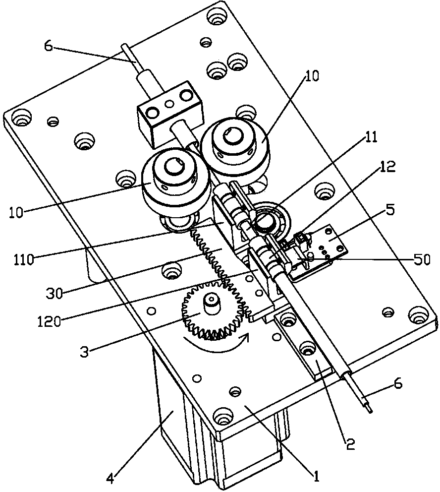
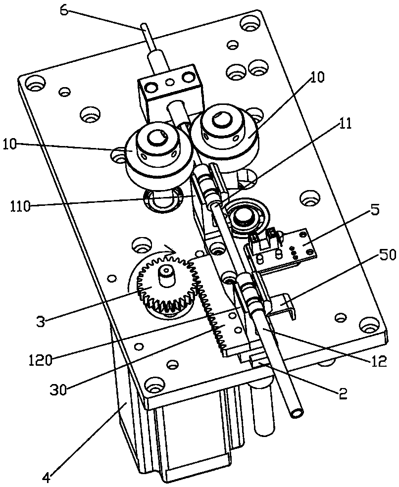
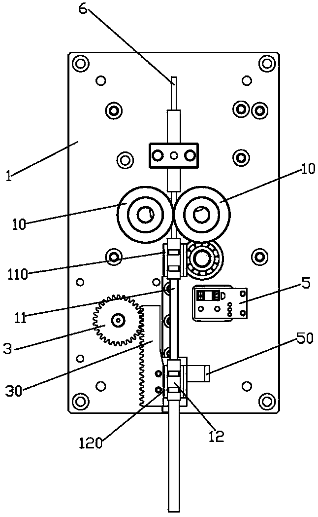
[0015] refer to figure 1 to Figure 3 ( figure 1 , figure 2 The direction of the middle arrow indicates the direction of rotation of the drive gear), a wire feeding mechanism capable of extending the wire feeding stroke, including an upper panel 1 with a wire feeding wheel 10 on the surface, and a wire feeding wheel 10 is provided at the outlet of the wire feeding wheel 10. The first conduit 11 of the wire, the first conduit 11 is fixedly installed on the upper panel 1 through the first nozzle bracket 110, and the first conduit 11 is also movably sleeved with a second conductor that can move relative to it Pipe 12, the second wire pipe 12 is slidably installed on the guide rail 2 through the second nozzle bracket 120, and the guide rail 2 is fixedly installed on the upper panel 1, and the side wall of the second nozzle bracket 120 is fixedly provided with teeth A bar 30, one side of the rack 30 is provided with a drive gear 3 for driving it to move back and forth along the g...


PUM


Abstract

The invention discloses a wire feeding mechanism capable of prolonging the wire feeding travel. The wire feeding mechanism comprises an upper panel of which the surface is provided with a wire feeding wheel, wherein the wire outlet of the wire feeding wheel is provided with a first wire guide pipe; a second wire guide pipe is movably sleeved on the first wire guide pipe, and is arranged on a guide rail in a sliding way through a second wire nozzle bracket; a rack is fixedly arranged on one side wall of the second wire nozzle bracket; one side of the rack is provided with a driving gear for driving the rack to move forward and backward along the guide rail. By adopting a structure in which the first wire guide pipe is sleeved together with the second wire guide pipe in the wire feeding mechanism, the second wire guide pipe can move forward to feed wires together with the first wire guide pipe, thereby prolonging the wire feeding travel of the wire feeding mechanism. When wire feeding is not needed, the second wire guide pipe can move backwards to be sleeved and overlapped together with the first wire guide pipe, thereby reducing the occupied space of the wire feeding mechanism.

Description

technical field [0001] The invention relates to a wire feeding mechanism, in particular to a wire feeding mechanism capable of extending the wire feeding stroke. Background technique [0002] At present, most of the wire feeding mechanism and the tool holder adopt a separate structure. When the distance between the wire feeding mechanism and the tool holder is too far, because the wire feeding stroke of the traditional wire feeding mechanism is relatively short, the After the wire conveyed by the mechanism leaves the wire feeding mechanism for a certain distance, the free end of the wire will sag due to the gravity of the wire itself, so the traditional wire feeding mechanism cannot accurately send the wire to the tool holder, so the wire feeding distance of the wire feeding mechanism It has become a short board, which has brought a certain impact on the production and manufacturing of the enterprise. Contents of the invention [0003] In order to solve the above problems...

Claims


Application Information

Patent Timeline
Patent Type & Authority Applications(China)
IPC IPC(8): B65H57/12B65H63/00
Inventor 赵维陈杰
Owner 烟台力量知识产权服务有限公司
Learn More