Integrated type automatic thread screwing-unscrewing device

An integrated and automatic technology, applied in drilling equipment, earth-moving drilling, drill pipe, etc., can solve the problems of high labor intensity, low effective torque, unsafe, etc. Effect

Inactive Publication Date: 2014-04-23
JIANGSU WUXI MINERAL EXPLORATION MASCH GENERAL FAB CO LTD
View PDF6 Cites 5 Cited by
  • Summary
  • Abstract
  • Description
  • Claims
  • Application Information

AI Technical Summary

Problems solved by technology

[0002] In the structure of the traditional drilling rig, the hole part (that is, the part where the drill pipe is disassembled) is very simple. Often, there is no such structure or only a steel plate with a limit column is installed, and the joint of the drill pipe is clamped manually with a fork plate, and then started. The power head of the drilling rig is rotated to unscrew the thread. This manual method is labor-intensive and unsafe
[0003] Later, there were improved clamping structures, but there was no unscrewing device. Only when the drill pipe needs to be unscrewed, the oil cylinder on the clamp clamps one of the joints, and then the power head of the drilling rig is turned to unscrew the thread. This structure The original fork wrench has been improved, but relying on the rotation of the power head to unscrew the thread, the distance is long and the effective torque is small. In actual use, there are still defects such as unscrewing and low efficiency.

Method used


Image

  • Integrated type automatic thread screwing-unscrewing device
  • Integrated type automatic thread screwing-unscrewing device
  • Integrated type automatic thread screwing-unscrewing device

Examples


Embodiment Construction

[0019] Below the present invention will be further described in conjunction with the embodiment in the accompanying drawing:

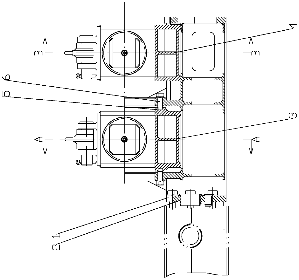
[0020] Such as Figure 1~4 As shown, the present invention mainly includes an installation body 1, a swing housing 3 and a fixed housing 4. The side of the installation body 1 is provided with a positioning sleeve 2 through which the mast is positioned and connected.

[0021] The installation body 1 is provided with a plurality of guide rail bolts 6, and the plurality of guide rail bolts 6 are arranged in sequence to form a semicircular swing guide rail. A semicircular swing guide groove 5 is provided on the swing housing 3 , and the swing housing 3 is slidably installed in the swing guide rail through the swing guide groove 5 . The housing 4 is fixed on the mounting body 1 by bolts.

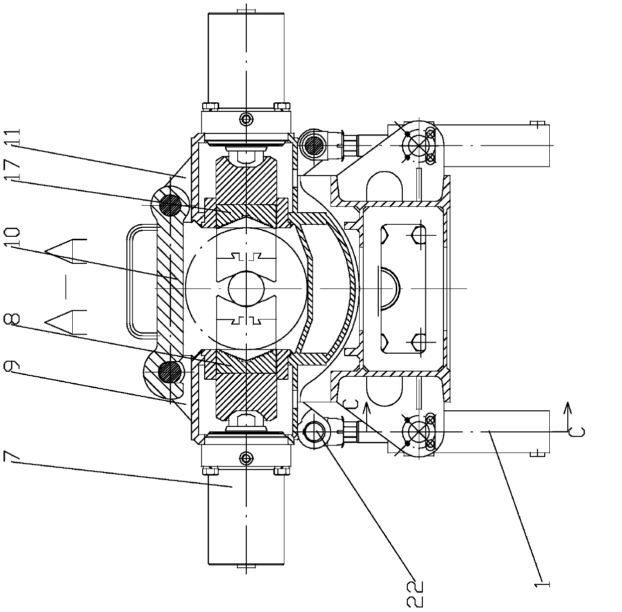
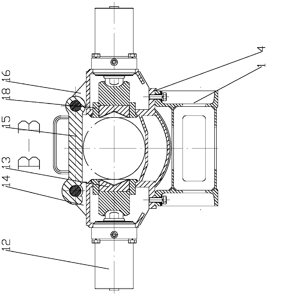
[0022] Two first clamping cylinders 7 are arranged opposite to each other on both sides of the swing housing 3 , and the front end of the piston rod of each first clam...


PUM


Abstract

The invention relates to an integrated type automatic thread screwing-unscrewing device, in particular to an automatic screwing-unscrewing device for a drill rod of a drill, and belongs to the technical field of drilling equipment. The device comprises a mounting member, a swing shell and a fixed shell. The mounting member is provided with a plurality of guide rail bolts which are arrayed sequentially to form a semicircular swing guide rail. The swing shell is provided with a semicircular swing guide groove and is slidably mounted in the swing guide rail through the swing guide groove. The mounting member is connected with the fixed shell through bolts. Two sides of the mounting member are respectively connected to swing cylinders through swing pins, each front end of piston rod of each swing cylinder is rotatably connected to a connecting pin of the lower end of the swing shell, and the two swing cylinders of two sides of the mounting member push the swing shell to swing along the semicircular swing guide rail. The device is convenient to use and can be used for automatic screwing and unscrewing the drill rod of a drill, screwing-unscrewing operation is efficient and reliable, and working intensity of operators is reduced greatly.

Description

technical field [0001] The invention relates to an integrated automatic unscrewing and unscrewing device, in particular to an automatic unscrewing and unscrewing device for drilling rods on a drilling rig, and belongs to the technical field of drilling rig equipment. Background technique [0002] In the structure of the traditional drilling rig, the hole part (that is, the part where the drill pipe is disassembled) is very simple. Often, there is no such structure or only a steel plate with a limit column is installed, and the joint of the drill pipe is clamped manually with a fork plate, and then started. The power head of the drilling rig is rotated to unscrew the threads. This manual method is labor-intensive and unsafe. [0003] Later, there were improved clamping structures, but there was no unscrewing device. Only when the drill pipe needs to be unscrewed, the oil cylinder on the clamp clamps one of the joints, and then the power head of the drilling rig is turned to u...

Claims


Application Information

Patent Timeline
Patent Type & Authority Applications(China)
IPC IPC(8): E21B19/18
Inventor 朱利根
Owner JIANGSU WUXI MINERAL EXPLORATION MASCH GENERAL FAB CO LTD
Why Eureka
Try Eureka