Double spring support pull type automatic filling valve float valve

An automatic grouting, double-spring technology, applied in wellbore/well components, earthwork drilling, flushing wellbore, etc., can solve the problems of incapable of automatic grouting torsion spring, easily damaged float valve, failure, etc. Blowout, time saving, low cost effect

Inactive Publication Date: 2014-04-23
慕武
View PDF0 Cites 0 Cited by
  • Summary
  • Abstract
  • Description
  • Claims
  • Application Information

AI Technical Summary

Problems solved by technology

Avoid the disadvantages of the current valve type float valve that cannot be automatically gr...

Method used


Image

  • Double spring support pull type automatic filling valve float valve

Examples


Embodiment Construction

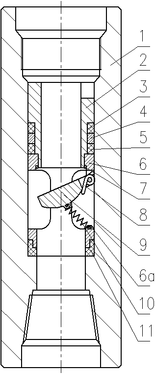
[0011] Such as figure 1 As shown, a double-spring support type automatic grouting valve float valve is composed of a float valve joint 1, a float valve and a valve support device. The float valve consists of an upper valve body 2, an upper sealing ring 3, a sealing gasket ring 4, a middle The sealing ring 5, the valve body seat 6, the valve sealing ring 7, the valve 9 and the lower sealing ring 11 are composed of the valve supporting device, which is composed of the valve supporting spring hook 6a, the support torsion spring 8 and the supporting spring 10, and the floating valve Placed in the float valve joint 1, the upper valve body 2 is connected with the valve body seat 6 with threads, the upper sealing ring 3, the gasket ring 4, and the middle sealing ring 5 are set on the upper valve body 2, and the valve sealing ring 7 is inlaid Installed in the groove of the valve body seat 6 at the closing position of the valve 9, the lower sealing ring 11 is set on the lower end of th...


PUM


Abstract

The invention discloses a double spring support pull type automatic filling valve float valve. The automatic filling valve float valve is characterized in that a float valve is arranged in a float valve joint, a valve is hinged to a valve seat of the float valve, the elastic force of a torsion spring which is supported on the valve and the valve seat can enable the valve to be closed up with the valve seat when the valve is in a free state, the principle that the holding force and pulling force of a tension spring are used for balancing the elastic force of the torsion spring when an automatic closing valve type float valve is closed, and the force which flows into a pipe and is caused by liquid column pressure difference inside and outside the pipe can make the valve be always in an ajar state, a fluid flow passage is formed, and the purpose of automatic filling is achieved. When kick or blowout happens in the pipe, the tension spring of the valve is lengthened under the action of flowing liquid in the pipe. The valve is closed, and plays the action of a single flow valve. The problem of being unable to automatically fill of the existing valve type float valve is solved. The tension spring and the torsion spring are replaced and the force and the length of the springs are adjusted before the drilling tool is run into a well every time; the double actions of the double springs avoid the abuse of losing effectiveness of the float valve after the torsion spring is easily broken.

Description

technical field [0001] The invention relates to the method of manual grouting without stopping the drilling (oil pipe running) operation in the oil drilling process, which can be automatically grouted. When the flow velocity of the fluid in the pipe such as well kick and blowout reaches a certain value, it will play the role of a check valve, which can prevent the occurrence of blowout accidents in the pipe. Background technique [0002] In the process of oil drilling (tubing running), the commonly used valve type float valve only plays the role of a check valve, and because of the limitation of the pressure bearing capacity and the compression strength of the drill pipe (tubing), the running (running) When the oil pipe) reaches a certain well depth, in order to prevent the valve type float valve from being invalid due to the excessive pressure, it is easy to cause well kick or even blowout accident in the pipe, prevent the drill pipe (oil pipe) from being crushed and cause ...

Claims


Application Information

Patent Timeline
IPC IPC(8): E21B21/10
Inventor 张勇马振勇王星张明辉许洋姜双奎彭海军张晓刚王鹏程宋文婷慕武
Owner 慕武
Why Eureka
Try Eureka