Continuous carbonization equipment and material conveying device

A technology for conveying devices and materials, which is applied in the field of carbonization treatment equipment, and can solve problems that affect the working efficiency of carbonization treatment equipment, cannot continue to be used, and the service life of material conveying devices is short.

Inactive Publication Date: 2014-04-23
ADVANCED FOR MATERIALS & EQUIP
View PDF10 Cites 1 Cited by
  • Summary
  • Abstract
  • Description
  • Claims
  • Application Information

AI Technical Summary

Problems solved by technology

[0003] At present, in the assembly structure of the existing material conveying device, it mainly uses the metal mesh belt as the conveying carrier to complete the corresponding material conveying operation. However, although this kind of metal mesh belt conveying The metal material is very easy to have carburizing reaction with the carbon atmosphere in the working environment at high temperature, causing its material to become brittle and unable to continue to be used. Usually, the metal mesh belt needs to be replaced in only three months, causing the material conveying device to The short service life not only seriously affects the working efficiency of the entire carbonization treatment equipment, but also leads to a corresponding increase in its use cost

Method used


Image

  • Continuous carbonization equipment and material conveying device

Examples


Embodiment Construction

[0015] The core of the present invention is to provide a material conveying device, which has a long service life and can improve the working efficiency of the continuous carbonization equipment; at the same time, it provides a continuous carbonization equipment using the above material conveying device.

[0016] In order to enable those skilled in the art to better understand the solution of the present invention, the present invention will be further described in detail below in conjunction with the accompanying drawings and specific embodiments.

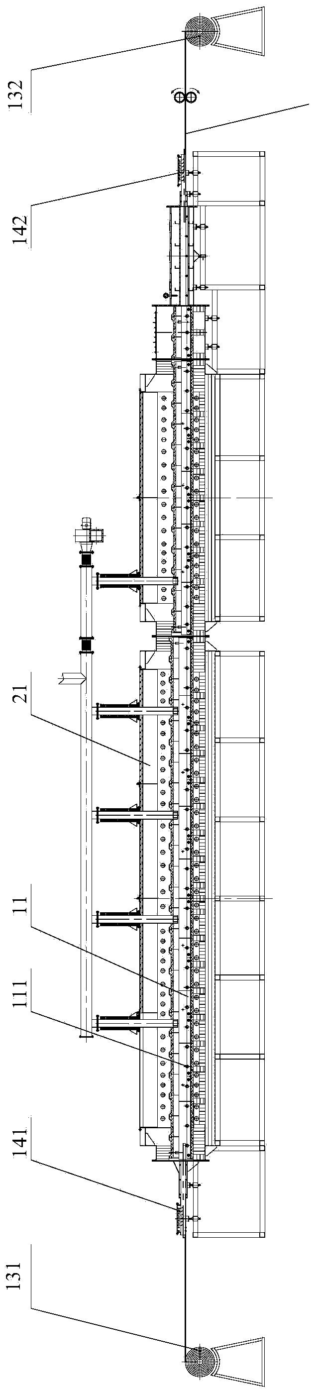
[0017] Please refer to figure 1 , figure 1 It is a schematic diagram of the assembly structure of the continuous carbonization equipment provided by a specific embodiment of the present invention.

[0018] In a specific embodiment, the material conveying device provided by the present invention includes a conveying track 11 arranged horizontally, and several corundum trustees 111 are arranged on the conveying track 11 along the h...


PUM


Abstract

The invention discloses a material conveying device which comprises a horizontal conveying rail. A plurality of corundum support tubes are arranged on the conveying rail along the horizontal direction, an extension direction of an axis of each corundum support tube is perpendicular to a conveying direction of the conveying rail, the corundum support tubes are sequentially uniformly distributed along the conveying direction of the conveying rail, and carbon fiber pre-oxidation felt matched with the corundum support tubes is arranged above the conveying rail. In the working process, the corundum support tubes cannot react with a surrounding carbon atmosphere, the material conveying device is high in structural strength, whole service life of the material conveying device can be remarkably prolonged, structural reliability of the material conveying device can be remarkably improved, and overall working efficiency of continuous carbonization equipment is improved correspondingly. The invention further discloses the continuous carbonization equipment applying the material conveying device.

Description

technical field [0001] The invention relates to the technical field of carbonization treatment equipment, in particular to a material conveying device. The invention also relates to a continuous carbonization equipment using the material conveying device. Background technique [0002] Continuous carbonization equipment is a very common carbonization treatment equipment, and the material conveying device is an indispensable working component in the main structure of continuous carbonization equipment, and its working performance is also increasingly concerned by people. [0003] At present, in the assembly structure of the existing material conveying device, it mainly uses the metal mesh belt as the conveying carrier to complete the corresponding material conveying operation. However, although this kind of metal mesh belt conveying The metal material is very easy to have carburizing reaction with the carbon atmosphere in the working environment at high temperature, causing i...

Claims


Application Information

Patent Timeline
Patent Type & Authority Applications(China)
IPC IPC(8): F27B9/20F27B9/30
Inventor 戴煜胡祥龙蒋振宇
Owner ADVANCED FOR MATERIALS & EQUIP
Why Eureka
Try Eureka