Combined linear flow velocity and temperature field measurement gun for flue gas in flue

A flue gas temperature, measuring gun technology, applied to measuring devices, instruments, etc., can solve the problems of difficulty in ensuring the accuracy and reliability of flow velocity data, inability to measure flow velocity at the same time, and large workload, achieving simple structure and reducing turbulence. , the effect of convenient operation

Inactive Publication Date: 2014-04-23
HUBEI ENVIRONMENT MONITORING CENT STATION
View PDF7 Cites 1 Cited by
  • Summary
  • Abstract
  • Description
  • Claims
  • Application Information

AI Technical Summary

Problems solved by technology

However, the flow velocity of flue gas in the flue is mainly affected by the working conditions, and the isocyclic area method uses multi-point moving test, which cannot measure the flow velocity of each point on the same section at the same time
Therefore, it is difficult to guarantee the accuracy and reliability of the measured flow rate data by using the equal-circle area method.
Moreover, the area of ​​the rectangular flue is 4.0-9.0 / m by the equal-ring area method. 2 , the total number of measuring points needs to be 9-16 / piece, and the circular flue diameter of 3-5m needs to be divided into 5 rings, 10 measuring points, long cycle and heavy workload

Method used


Image

  • Combined linear flow velocity and temperature field measurement gun for flue gas in flue
  • Combined linear flow velocity and temperature field measurement gun for flue gas in flue

Examples


Embodiment Construction

[0013] The present invention will be described in further detail below in conjunction with the accompanying drawings.

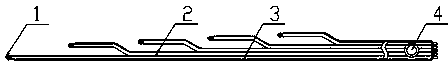
[0014] As shown in the attached picture,

[0015] A combined measuring gun for flue gas linear flow velocity and flue gas temperature field in a flue, including an S-shaped pitot tube 2 in the measuring gun and a sensor joint connecting the static pressure tube and the total pressure tube of the S-shaped pitot tube 2 and the S-shaped pitot tube. The temperature sensor 4 on the Pitot tube 2, the measuring gun is composed of more than four pairs of S-type Pitot tubes 2, and more than four pairs of S-type Pitot tubes 2 are parallel to each other. The distance between 1 is 200mm, each S-shaped pitot tube 2 is bent at 100mm from the measuring head, the bending angle is 5°-10°, after bending, the centerline of the measuring head and the centerline of the pitot tube body are parallel to each other , and the vertical distance is more than 15mm, and each S-shaped pit...


PUM


Abstract

The invention relates to a combined linear flow velocity and temperature field measurement gun for flue gas in a flue. The measurement gun is mainly used for synchronously measuring the flow velocity and the temperature of the flue gas at each point in the flue according to different flue sectional areas, and belongs to an environment monitor. The measurement gun is formed by combining more than four pairs of S-shaped pitot tubes and temperature sensors, wherein a distance between measurement holes of measurement heads of every two adjacent S-shaped pitot tubes is 200mm; the part, which is 100mm away from the corresponding measurement head, of each S-shaped pitot tube is bent by a bending angle of 5 to 10 degrees; after the pitot tubes are bent, the centerlines of the measurement heads are parallel to the centerlines of tube bodies of the pitot tubes, and are at perpendicular distances of more than 15mm away from the centerlines of the tube bodies of the pitot tubes; the temperature sensors of which the lengths are the same as those of the S-shaped pitot tubes are arranged on the S-shaped pitot tubes. The measurement gun is simple in structure and convenient to operate; the problems, which cannot be solved by a conventional measurement gun, of synchronous measurement of linear flow velocity and temperature of the flue gas in the flue are solved, and the flow velocity and the temperature of the flue gas at multiple points in a pollution source-fixed flue are simultaneously and synchronously measured at an equal interval on the same section.

Description

technical field [0001] The invention relates to a detection device for flue gas linear flow velocity and flue gas temperature in a fixed pollution source flue, and mainly relates to a combined flue gas linear flow velocity and flue gas temperature field measuring gun in a flue, which belongs to the category of environmental monitoring instruments. Background technique [0002] At present, the measurement of flue gas velocity in the flue of fixed pollution sources usually adopts the single-point and moving measurement method of S-type pitot tube. The two measuring heads on the S-type pitot tube have two openings in opposite directions, and the two opening sections are parallel to each other. When measuring, the opening facing the airflow direction measures the total pressure, and the opening facing away from the airflow direction measures the static pressure. Due to the structure of the pitot tube, the flow velocity distribution of the flue gas in the flue is dynamically ch...

Claims


Application Information

Patent Timeline
Patent Type & Authority Applications(China)
IPC IPC(8): G01D21/02
Inventor 田一平王国贵全继宏罗四国陶骏刘真贞王强杨凯
Owner HUBEI ENVIRONMENT MONITORING CENT STATION
Why Eureka
Try Eureka