Target positioning and tracking system based on visible light communication and CCRs (Cube Corner Retro-reflectors)

A technology of visible light communication and target positioning, which is applied in radio wave measurement system, re-radiation of electromagnetic waves, utilization of re-radiation, etc., can solve problems such as limited detection range, increased cost, and low precision, and achieve strong system stability, The effect of low modification difficulty and high precision

Inactive Publication Date: 2014-04-23
明华智讯(天津)科技有限公司
View PDF5 Cites 11 Cited by
  • Summary
  • Abstract
  • Description
  • Claims
  • Application Information

AI Technical Summary

Problems solved by technology

These methods have their own advantages and disadvantages: the cost of using GPS is lower, but requires users to carry special equipment, and the signal of GPS is weak indoors or in the center of the urban area, which is almost unusable; the solution of using camera sensor realizes passive tracking and positioning , without the need for users to carry special equipment, but the cost of the solution is high and the cost will continue to increase with the increase of the coverage area. At the same time, it needs to cooperate with the image recognition algorithm to identify the user, and the accuracy is low; the use of RFID solutions is limited by the detection range of RFID. The detection range is small
[0003] In some scenarios, the above-mentioned solutions are not very applicable. For example, for the positioning and tracking of miners or mine vehicles in mines, radio frequency communication cannot be used in mines, and there is no GPS signal, and the cost of camera monitoring is high; another example is in large public areas. (Airports, stations, museums, gymnasiums, etc.) for the location tracking of security personnel / staff. There is no GPS signal in this indoor area, and the dense flow of people makes it difficult to identify the camera. The movement range of the tracked personnel is large and RFID continuous tracking is not applicable

Method used


Image

  • Target positioning and tracking system based on visible light communication and CCRs (Cube Corner Retro-reflectors)
  • Target positioning and tracking system based on visible light communication and CCRs (Cube Corner Retro-reflectors)
  • Target positioning and tracking system based on visible light communication and CCRs (Cube Corner Retro-reflectors)

Examples


Embodiment Construction

[0017] The implementation of the present invention will be described in detail below in conjunction with the drawings and examples.

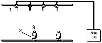
[0018] Such as figure 2 As shown, a target positioning and tracking system based on visible light communication and CCR includes multiple LED lamps 1 with different numbers and multiple corner cube modulators 2 with different numbers. The LED lamps 1 illuminate downward and have For larger divergence angles, the corner cube modulator 2 is carried by the target 3 .

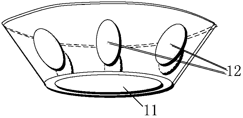
[0019] Such as image 3 As shown, LED lamp 1 includes lighting LED 11 and several photodetectors (PD) 12 with different numbers. a circle.

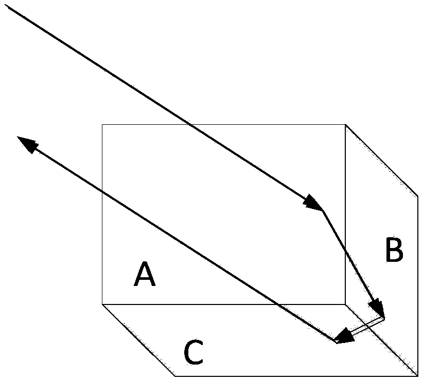
[0020] The tracked target 3 needs to carry special equipment, and the core of the special equipment is the corner cube modulator 2 . The corner cube modulator 2 can be, but not limited to, manufactured by MEMS technology, and its working principle has been described in the background technology. A plane of the corner cube modulator 2 can be...


PUM


Abstract

The invention discloses a target positioning and tracking system based on visible light communication and CCRs (Cube Corner Retro-reflectors). The target positioning and tracking system comprises a plurality of LED (Light-Emitting Diode) lamps with different numbers and a plurality of CCRs with different numbers, wherein each LED lamp comprises an illuminating LED and a plurality of photoelectric detectors with different numbers; when light rays emitted by a certain illuminating LED enter the reflecting surface of a certain CCR, the CCR is used for modulating the number of the CCR into reflected light for transmitting outwards; the number information is received by the photoelectric detector on the LED lamp and is transmitted to a control center, and the position of the CCR is judged by using the control center according to the numbers of the LED lamp, the CCR and photoelectric detector. The target positioning and tracking system works in an LED illumination covering area, is used for positioning and tracking a target carrying a special receiver, and has the characteristics of freeness from radiofrequency radiation, low cost, low refitting difficulty, high system stability, high precision and the like.

Description

technical field [0001] The invention belongs to the technical field of target positioning, in particular to a target positioning and tracking system based on visible light communication and CCR. Background technique [0002] Target tracking and positioning has a wide range of application requirements in many occasions. Some existing positioning tracking methods include: using the GPS positioning module carried by the user to obtain user location information, and sending it back to the control center through wireless communication; using the camera network to obtain user information , and send it back to the control center through the wired network; use RFID technology to locate and track the location of the user carrying the RFID module. These methods have their own advantages and disadvantages: the cost of using GPS is lower, but requires users to carry special equipment, and the signal of GPS is weak indoors or in the center of the urban area, which is almost unusable; the...

Claims


Application Information

Patent Timeline
Patent Type & Authority Applications(China)
IPC IPC(8): G01S17/06G01S17/66
CPCG01S17/06G01S17/66
Inventor 余冰雁张洪明
Owner 明华智讯(天津)科技有限公司
Why Eureka
Try Eureka