A control signal generation circuit
A technology for controlling signals and generating circuits, applied in the field of signal processing, can solve the problems of high manufacturing cost and occupying input and output ports of startup control equipment, and achieve the effects of reducing manufacturing cost and software cost, not easy to be interfered by external environment, and accurate results.
- Summary
- Abstract
- Description
- Claims
- Application Information
AI Technical Summary
Problems solved by technology
Method used
Image

Examples
Embodiment 1
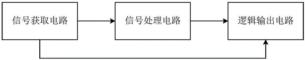
[0047]The technical solution of this embodiment is: a control signal generating circuit, which is used to generate a control signal of the second device according to the pulse signal of the first device, so that the second device is turned on with a delay relative to the first device and turned off in advance; The first device mentioned above is a signal receiving or sensing device such as an LED lamp, an infrared lamp or a sensor; the second device is a signal collecting device such as a camera, an audio collector (such as a device for collecting voice), a distance detector or a temperature detector. The control signal generation circuit includes:
[0048] 1. A signal acquisition circuit, configured to acquire the pulse signal of the first device;
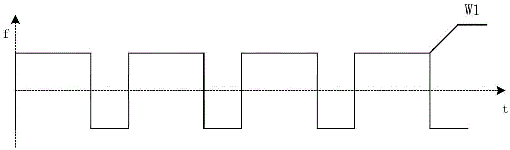
[0049] 2. A signal processing circuit, configured to delay the rising edge of the pulse signal to obtain the first signal; and perform an advance operation on the falling edge of the pulse signal to obtain the second signal;
[0...
Embodiment 3
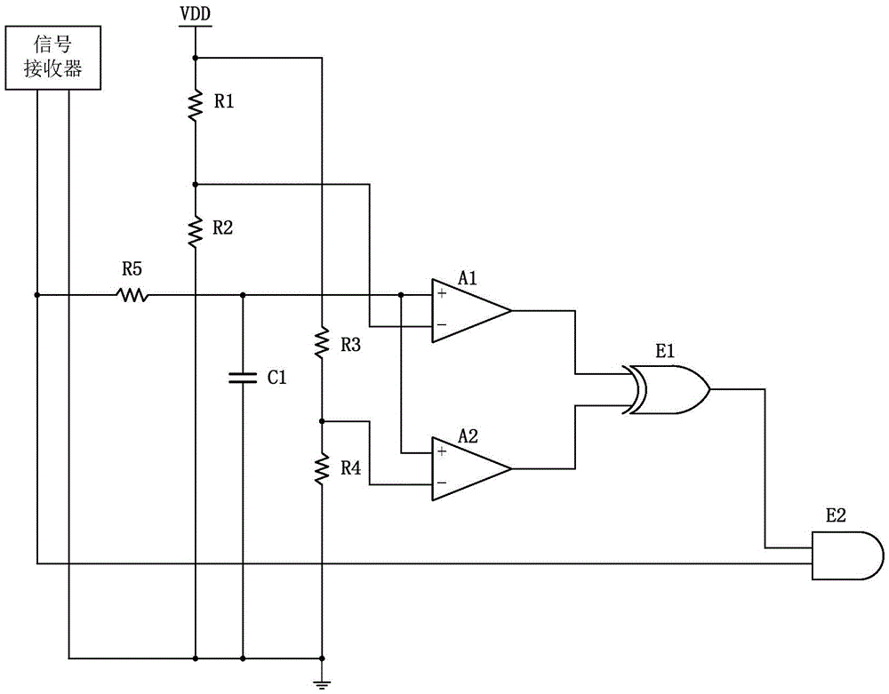
[0084] The control signal generation circuit provided in this embodiment further includes an execution circuit; the execution circuit is configured to control the second device through the control signal of the second device.
[0085] The actuating circuit is usually a switching element or a motor element. The executive circuit in this embodiment includes a sixth resistor and a transistor; the sixth resistor R6 is used to limit the current; the transistor D1 is used to act according to the waveform W6.
[0086]The first terminal of the sixth resistor R6 is connected to the output terminal of the second logic circuit (that is, the output terminal of the AND gate E2); the second terminal of the sixth resistor R6 is connected to the output terminal of the transistor D1 The base is connected; the collector of the triode D1 is connected to the second device; the emitter of the triode D1 is grounded.
[0087] An actual circuit connection diagram of this embodiment is shown as Fig...
PUM
 Abstract
Description
Claims
Application Information