SMD type t-shaped biped linear piezoelectric ultrasonic motor vibrator

A piezoelectric ultrasonic and patch-type technology, which is applied in the direction of piezoelectric effect/electrostrictive or magnetostrictive motors, generators/motors, electrical components, etc., can solve the problems of complex driving methods, idle waste of vibration energy, etc. , to achieve the effect of simple excitation method, simple processing and assembly, and simplified structure

Active Publication Date: 2017-03-01
HARBIN INST OF TECH
View PDF5 Cites 0 Cited by
  • Summary
  • Abstract
  • Description
  • Claims
  • Application Information

AI Technical Summary

Problems solved by technology

[0004] The present invention is to solve the problems of idle waste of vibration energy, complicated driving method and vibration coupling existing in the existing T-type linear ultrasonic motor vibrator, and now provides a patch-type T-type biped linear piezoelectric ultrasonic motor vibrator

Method used


Image

  • SMD type t-shaped biped linear piezoelectric ultrasonic motor vibrator
  • SMD type t-shaped biped linear piezoelectric ultrasonic motor vibrator
  • SMD type t-shaped biped linear piezoelectric ultrasonic motor vibrator

Examples


specific Embodiment approach 1

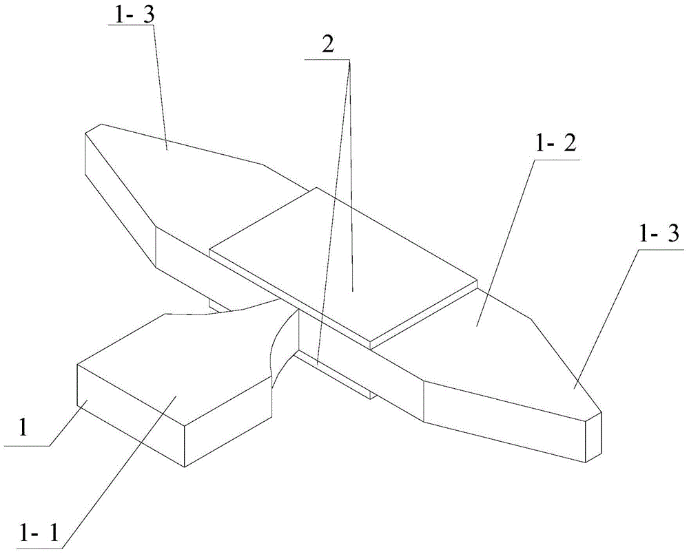
[0023] Specific implementation mode one: refer to figure 1 Specifically explain this embodiment, the chip-type T-shaped biped linear piezoelectric ultrasonic motor vibrator described in this embodiment includes a base 1 and two piezoelectric ceramic sheets 2;

[0024] The base 1 includes: a longitudinal beam 1-1, a cross beam 1-2 and two horns 1-3;

[0025] The shape of the beam 1-2 is a cuboid;

[0026] The horn 1-3 is a block with gradually smaller cross section,

[0027] One end of the longitudinal beam 1-1 is vertically fixed on one side of the cross beam 1-2, so that the longitudinal beam 1-1 and the cross beam 1-2 form a T-shaped structure;

[0028] The two ends of the beam 1-2 are respectively provided with a horn 1-3, and the big end of the horn 1-3 is fixedly connected with the beam 1-2;

[0029] Two piezoelectric ceramic sheets 2 are respectively fixed on the upper and lower surfaces of the beam 1-2;

[0030] The two piezoelectric ceramic sheets 2 are both polar...

specific Embodiment approach 2

[0033] Embodiment 2: This embodiment is a further description of the chip-type T-shaped biped linear piezoelectric ultrasonic motor vibrator described in Embodiment 1. In this embodiment, the base 1 is an integrated structure.

[0034] In this embodiment, the longitudinal beam 1-1, the cross beam 1-2 and the two horns 1-3 are integrated, which can simplify the processing and assembly process.

specific Embodiment approach 3

[0035] Specific embodiment three: This embodiment is a further description of the chip-type T-shaped bipedal linear piezoelectric ultrasonic motor vibrator described in specific embodiment one or two. In this embodiment, the two piezoelectric ceramic sheets 2 The shapes are exactly the same, and the area of ​​the cross-section of the piezoelectric ceramic sheet 2 is smaller than or equal to the area of ​​the surface of the beam 1-2 where the piezoelectric ceramic sheet 2 is located.

[0036] In this embodiment, the piezoelectric ceramic sheet 2 is a block with a cross-sectional area smaller than or equal to the cross-sectional area of ​​the beam 1-2, which is conducive to efficient excitation of longitudinal vibration.


PUM


Abstract

A paster T-shaped dual-feet linear piezoelectric supersonic motor vibrator belongs to the technical field of piezoelectric supersonic motors and aims to solve the problems of idled and wasted vibration energy, a complex driving method and vibration coupling existing in the existing T-shaped linear supersonic motor vibrator. According to the paster T-shaped dual-feet linear piezoelectric supersonic motor vibrator, a small end surface of a longitudinal beam is vertically fixed on one surface of a crossbeam; the longitudinal beam and the crossbeam form a T-shaped structure; variable amplitude rods are arranged at two ends of the crossbeam; the large ends of the variable amplitude rods are fixedly connected with the crossbeam; two piezoelectric ceramic pieces are respectively fixed on the upper end surface and the lower end surface of the crossbeam; the two piezoelectric ceramic pieces are polarized along the thickness direction and the polarization directions of the two piezoelectric pieces are opposite. The variable amplitude rods at two sides are used for actuating output without the problem of the idled and wasted energy. The vibration coupling problem is avoided due to the longitudinal vibration of one crossbeam, so the motor performances are improved. The paster T-shaped dual-feet linear piezoelectric supersonic motor vibrator is suitable for manufacturing a miniaturized piezoelectric supersonic motor.

Description

technical field [0001] The invention belongs to the technical field of piezoelectric ultrasonic motors. Background technique [0002] Piezoelectric ultrasonic motor is a kind of piezoelectric ultrasonic motor that uses the inverse piezoelectric effect of piezoelectric ceramics to excite vibration in the ultrasonic frequency range in the elastic body, and forms a particle motion with a specific trajectory at a specific point or area on the surface of the elastic body, and then passes through the stator, The frictional coupling between the rotors converts the microscopic motion of the particle into the macroscopic motion of the rotor. It has the advantages of simple structure, flexible design, low speed, high torque / thrust, high power / torque density, high positioning accuracy, fast response speed, and self-locking when power is off. , No electromagnetic interference and not subject to electromagnetic interference. [0003] In the patent application with the publication number...

Claims


Application Information

Patent Timeline
Patent Type & Authority Patents(China)
IPC IPC(8): H02N2/04
Inventor 刘英想陈维山冯培连刘军考石胜君
Owner HARBIN INST OF TECH
Why Eureka
Try Eureka