Paster bent vibration composite single-foot piezoelectric supersonic motor vibrator

A piezoelectric ultrasonic, composite technology, applied in piezoelectric effect/electrostrictive or magnetostrictive motors, generators/motors, electrical components, etc., can solve the problems of complex systems and unfavorable integration, and achieve large The effect of flexibility

Inactive Publication Date: 2014-04-23
HARBIN INST OF TECH
View PDF5 Cites 4 Cited by
  • Summary
  • Abstract
  • Description
  • Claims
  • Application Information

AI Technical Summary

Problems solved by technology

[0004] The purpose of the present invention is to solve the problem that the current ultrasonic motor vibrator adopts a double-drive foot structure, and it needs to be assisted by two sets of movers and guide rail systems to realize the drive, which will make the system complicated and not conducive to the realization of integration. The present invention Provide a patch type bending vibration composite single-foot piezoelectric ultrasonic motor vibrator

Method used


Image

  • Paster bent vibration composite single-foot piezoelectric supersonic motor vibrator
  • Paster bent vibration composite single-foot piezoelectric supersonic motor vibrator
  • Paster bent vibration composite single-foot piezoelectric supersonic motor vibrator

Examples


specific Embodiment approach 1

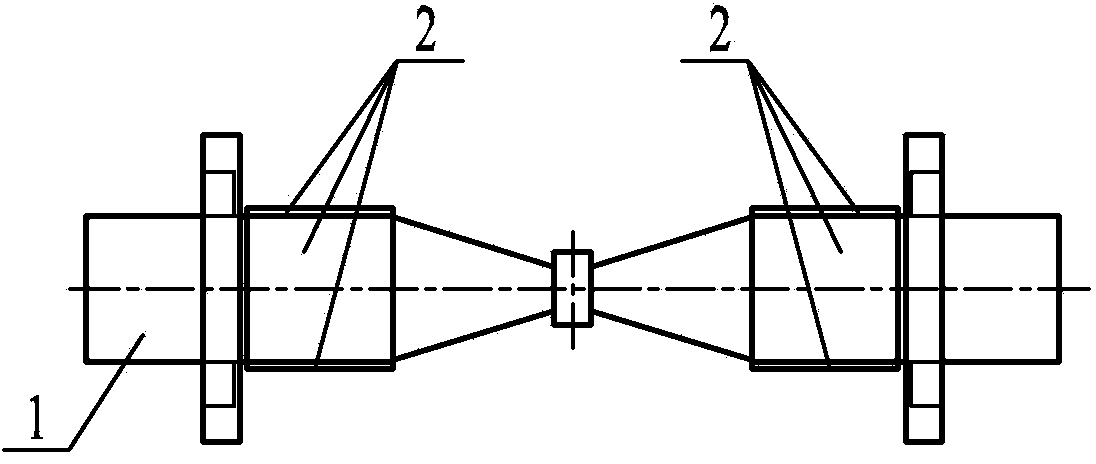
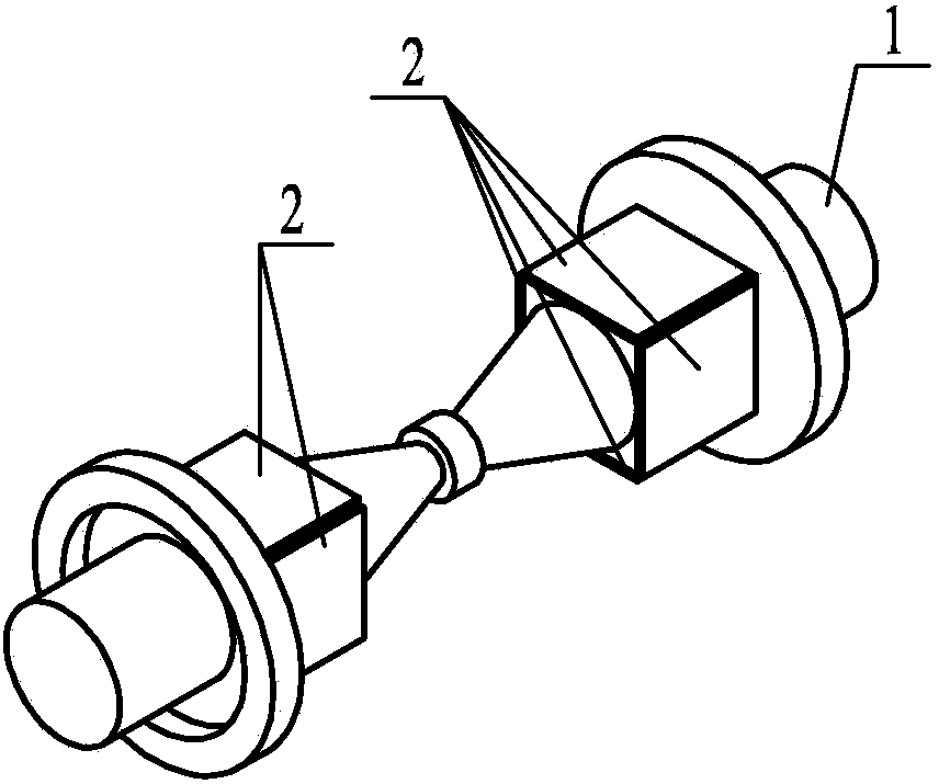
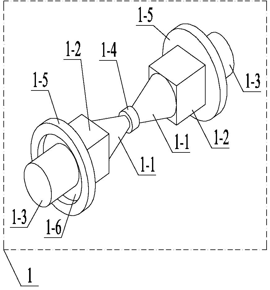
[0019] Specific implementation mode one: combine Figure 1 to Figure 7 Describe this embodiment, the chip-type flexural-vibration composite single-foot piezoelectric ultrasonic motor vibrator described in this embodiment includes a metal base 1 and eight piezoelectric ceramic sheets 2; the metal base 1 includes two amplitude-changing Rod 1-1, two intermediate beams 1-2, two rear end covers 1-3, driving feet 1-4 and two flanges 1-5;

[0020] The horn 1-1 is a block that gradually becomes thinner from the head end to the end, the middle beam 1-2 is a cuboid with a square cross section, and the head ends of the two horns 1-1 are connected with the two middle beams 1-2 is fixedly connected at the head end surface, and the ends of the two horns 1-1 are fixedly connected through the driving foot 1-4, and a rear end cover 1-3 is provided at the end surface of each intermediate beam 1-2, A flange 1-5 is provided on the outer side of each rear end cover 1-3;

[0021] A piezoelectric ...

specific Embodiment approach 2

[0023] Specific embodiment 2: This embodiment is a further limitation of the patch type bending vibration composite single-foot piezoelectric ultrasonic motor vibrator described in specific embodiment 1. The two horns 1-1, two middle The metal base 1 composed of beam 1-2, two rear end covers 1-3, driving foot 1-4 and two flanges 1-5 is one piece, which greatly simplifies the manufacturing process of the ultrasonic motor vibrator.

specific Embodiment approach 3

[0024] Embodiment 3: This embodiment is a further limitation of the patch type bending vibration composite single-foot piezoelectric ultrasonic motor vibrator described in Embodiment 1. Each flange 1-5 and the corresponding rear end cover 1- 3 are fixedly connected by thin-walled rings 1-6. The thin-walled rings 1-6 are used to achieve the effects of elastic support and vibration isolation, and can minimize the influence of the connection between the vibrator and other components on the vibration of the vibrator itself.


PUM


Abstract

A paster bent vibration composite single-foot piezoelectric supersonic motor vibrator belongs to the technical field of piezoelectric supersonic motors and aims to solve the problem that the integration is unfavorably realized due to a complex system as the existing supersonic motor vibrator adopts a dual-driving feet structure and is assisted with two sets of rotors and a guide rail system for realizing driving. The paster bent vibration composite single-foot piezoelectric supersonic motor vibrator comprises two variable amplitude rods, two middle beams, two rear end covers, a driving foot, two flanges and eight piezoelectric ceramic pieces; each variable amplitude rod is a block body gradually thinned from the head end to the tail end; each middle beam is a cuboid with a square section; head ends of the two variable amplitude rods are connected with the head ends of the two middle beams; the tail ends of the two variable amplitude rods are connected by the driving foot; a rear end cover is arranged at the tail end surface of each middle beam; a flange is arranged outside each rear end cover; one piezoelectric ceramic piece is arranged on each side surface of each middle beam; the piezoelectric ceramic pieces are polarized along the thickness direction; the mutually parallel four piezoelectric ceramic pieces are same in the polarization direction. The paster bent vibration composite single-foot piezoelectric supersonic motor vibrator is suitable for the piezoelectric supersonic motor needing integration.

Description

technical field [0001] The invention relates to a patch-type bending-vibration composite single-foot piezoelectric ultrasonic motor vibrator, which belongs to the technical field of piezoelectric ultrasonic motors. Background technique [0002] Piezoelectric ultrasonic motor is a kind of piezoelectric ultrasonic motor that uses the inverse piezoelectric effect of piezoelectric ceramics to excite vibration in the ultrasonic frequency range in the elastic body, and forms a particle motion with a specific trajectory at a specific point or area on the surface of the elastic body, and then passes through the stator, The frictional coupling between the rotors converts the microscopic motion of the particle into the macroscopic motion of the rotor. It has the advantages of simple structure, flexible design, low speed, high torque / thrust, high power / torque density, high positioning accuracy, fast response speed, and self-locking when power is off. , No electromagnetic interference a...

Claims


Application Information

Patent Timeline
Patent Type & Authority Applications(China)
IPC IPC(8): H02N2/04
Inventor 刘英想陈维山冯培连刘军考石胜君
Owner HARBIN INST OF TECH
Why Eureka
Try Eureka