Rectangular four-pin linear ultrasonic motor vibrator

A linear ultrasonic motor, rectangular technology, applied in the direction of generators/motors, piezoelectric effect/electrostrictive or magnetostrictive motors, electrical components, etc., can solve the problems of restricted mechanical output capacity, achieve flexible design, The structure is simple, and the effect of increasing the amplitude and vibration speed

Active Publication Date: 2012-08-15
HARBIN INST OF TECH
View PDF4 Cites 0 Cited by
  • Summary
  • Abstract
  • Description
  • Claims
  • Application Information

AI Technical Summary

Problems solved by technology

[0004] In order to solve the problem that the mechanical output capability of the stator of the ultrasonic motor that is excited by pasting the piezoelectric ceramic sheet with the metal elastic body is restricted, a rectangular quadruped linear ultrasonic motor vibrator is proposed.

Method used


Image

  • Rectangular four-pin linear ultrasonic motor vibrator
  • Rectangular four-pin linear ultrasonic motor vibrator
  • Rectangular four-pin linear ultrasonic motor vibrator

Examples


specific Embodiment approach 1

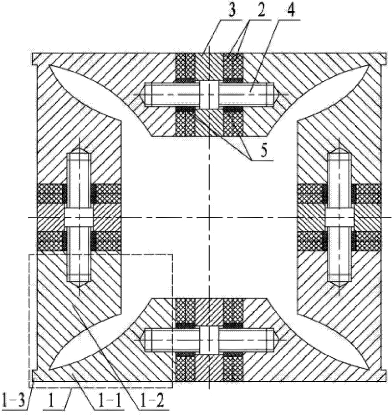
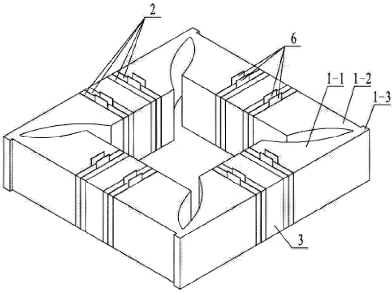
[0009] Specific implementation mode one: combine Figure 1 to Figure 4 Describe this embodiment, this embodiment is composed of four front end covers 1, eight pairs of piezoelectric ceramic sheets 2, four flanges 3, four pre-tightening studs 4, insulating sleeve 5 and eight pairs of electrode sheets 6; The structure and shape of the front end cover 1 are the same; the front end cover 1 is composed of a horizontal horn 1-1, a vertical horn 1-2 and a driving foot 1-3, and the horizontal horn 1-1 and the vertical Straight horns 1-2 are quadrangular prisms with a rectangular cross-section and gradually tapering, that is, one side of the quadrangular prism is an arc surface, and the other three sides are planar quadrangular prisms; the horizontal horn 1-1 and the center of the large end face of the vertical horn 1-2 have a blind hole with an internal thread, the driving foot 1-3 is a cuboid, and the bottom end surface of the driving foot 1-3 is aligned The end face of the small en...

specific Embodiment approach 2

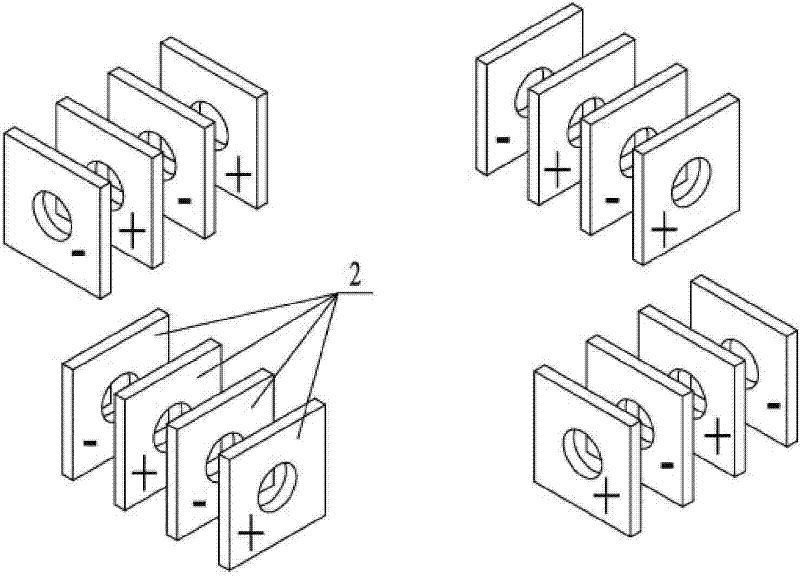
[0010] Embodiment 2: The difference between this embodiment and Embodiment 1 is that the polarization directions of the two piezoelectric ceramic sheets in each pair of piezoelectric ceramic sheets 2 on both sides of the flange 3 are opposite, and the horizontal horn 1 The polarization modes of the two groups of piezoelectric ceramic sheets 2 between -1 are opposite, and the polarization modes of the two groups of piezoelectric ceramic sheets 2 between the vertical horns 1-2 are the same. Other composition and connection methods are the same as those in the first embodiment.

specific Embodiment approach 3

[0011] Embodiment 3: The difference between this embodiment and Embodiment 1 is that the cross-section of the piezoelectric ceramic sheet 2 is square or circular.


PUM


Abstract

The invention relates to a rectangular four-pin linear ultrasonic motor vibrator, which relates to ultrasonic motor vibrators and solves the problem of limited output capability of the prior ultrasonic motor stator. The rectangular four-pin linear ultrasonic motor vibrator consists of four front end covers, eight pairs of piezoelectric ceramic plates, four flanges, four preloaded double-screw bolts, insulation bushes and electrode slices, wherein each front end cover comprises a horizontal horn, a vertical horn and a driving pin which is of a rectangle, the horizontal horn and the vertical horn are arranged in an orthogonal way, and the horizontal horn, the vertical horn and the driving pins are integrated pieces; big end faces of two adjacent horizontal horns are fixedly connected with the flanges via the preloaded double-screw bolts; a pair of piezoelectric ceramic plates is sleeved on a double-screw bolt arranged between the flanges and each horizontal horn, big end faces of two adjacent vertical horns are fixedly connected with the flanges via the preloaded double-screw bolts, and a pair of piezoelectric ceramic plates are sleeved on a double-screw bolt arranged between the flanges and each vertical horn. The invention can be applied to the field of ultrasonic motor manufacture.

Description

technical field [0001] The invention relates to an ultrasonic motor vibrator, in particular to a linear ultrasonic motor vibrator. Background technique [0002] Piezoelectric ultrasonic motor is a kind of piezoelectric ultrasonic motor that uses the inverse piezoelectric effect of piezoelectric ceramics to excite vibration in the ultrasonic frequency range in the elastic body, and forms a particle motion with a specific trajectory at a specific point or area on the surface of the elastic body, and then passes through the stator, The frictional coupling between the rotors converts the microscopic motion of the particle into the macroscopic motion of the rotor. It has the advantages of low speed and high torque, no need for a transmission mechanism, no electromagnetic interference, fast response, and self-locking when power is off. As a piezoelectric driver, it has Very wide range of applications. [0003] Due to the simplicity of the excitation principle and the simplicity o...

Claims


Application Information

Patent Timeline
Patent Type & Authority Patents(China)
IPC IPC(8): H02N2/04
Inventor 陈维山刘英想石胜君刘军考
Owner HARBIN INST OF TECH
Why Eureka
Try Eureka