
Methanation reactor

A methanation reactor and methane technology, applied in chemical instruments and methods, chemical/physical processes, etc., can solve the problems of increased equipment investment and energy consumption, complex manufacturing process, high reactor cost, etc., to achieve equipment investment and operating costs Low cost, reduce manufacturing cost, save preheating energy consumption effect

Active Publication Date: 2014-04-30
WUHUAN ENG
View PDF4 Cites 4 Cited by
  • Summary
  • Abstract
  • Description
  • Claims
  • Application Information

AI Technical Summary

Problems solved by technology

[0004] The methanation reaction is an important step in natural post-synthesis, which is mainly carried out in the methanation reactor. The existing methanation reactor mainly has a single-layer shell structure, which is filled with a methane catalyst. The raw material gas for the methanation reaction is produced by The upper inlet product is passed into the reactor, and through the catalyst layer, the product gas of the methanation reaction is discharged from the bottom of the reactor. Since the raw material gas introduced is high pressure and the methanation reaction is a strong exothermic reaction, high temperature methanation The wall of the reactor needs to withstand high temperature and high pressure at the same time, and the materials that can withstand high temperature and high pressure at the same time are of high grade, often expensive, and the reactor needs to be lined with a temperature-resistant layer, and the manufacturing process is complicated, resulting in high reactor cost. In this way, long-term use still has potential safety hazards
[0005] On the other hand, in the methanation reaction, there is a temperature requirement for the feed gas entering the catalyst bed, so the feed gas must be preheated to meet the requirements of the catalytic reaction, and the heating process also increases equipment investment and energy consumption

Method used


Image

  • Methanation reactor

Examples


Embodiment Construction

[0019] Below in conjunction with accompanying drawing, the present invention will be further explained:

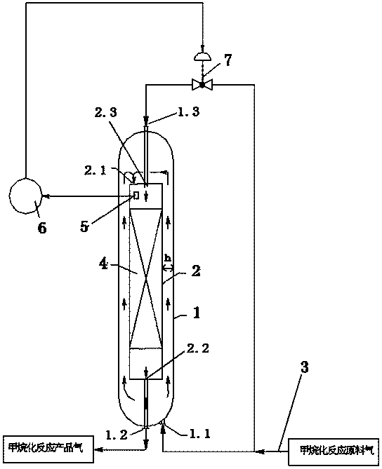
[0020] The bottom of the outer shell 1 is provided with an air inlet 1.1 and an outlet gas 1.2, and the outer shell 1 is also provided with an inner shell 2 filled with a methane catalyst bed 4, and the inner shell 1 The air inlet 2.1 of the body 2 is located at the top of the inner shell 2, and the air outlet 2.2 is located at the bottom of the inner shell 2 and is connected with the air outlet 1.2 of the outer shell 1. The distance between the inner shell 2 and the outer shell 1 is not less than 0.01m, and the optimal distance is 0.08-0.2m. The top of the outer shell 1 is also provided with a bypass air inlet 1.3, and the bypass air inlet 1.3 of the outer shell 1 is connected with the bypass air inlet 2.3 on the top of the inner shell 2. The air inlet 1.1 of the outer shell 1 and the bypass air inlet 1.3 are all connected to the raw material gas pipe 3, and the pipeline...


PUM


Abstract

The invention discloses a methanation reactor. The problems of high investment, high operation cost, large energy consumption and low reliability of the existing methanation reactor equipment are solved. According to the technical scheme, the methanation reactor comprises an outer shell, wherein an air inlet and an air outlet are formed in the outer shell; an inner shell filled with a methane catalyst bed is also arranged inside the outer shell; the air inlet and the air outlet of the outer shell are arranged at the bottom of the outer shell; the air inlet of the inner shell is arranged at the top of the inner shell; the air outlet is arranged at the bottom of the inner shell and connected with the air outlet of the outer shell. The methanation reactor is simple in structure, low in equipment investment, low in energy consumption and controllable in temperature of a raw material gas.

Description

technical field [0001] The invention relates to the field of methanation synthesis, in particular to a methanation reactor. Background technique [0002] With the implementation of my country's sustainable development strategy and environmental protection policies, the domestic demand for natural gas will increase day by day. In 2010, my country's natural gas demand was 110 billion Nm 3 , the market gap is about 20 billion Nm 3 , my country's natural gas demand in 2015 was 160 billion Nm 3 , the market gap is about 40 billion Nm 3 , the demand in 2020 is about 200 billion Nm 3 , with a gap of 80 billion Nm 3 above. [0003] Based on my country's basic national conditions of "more coal, less oil, and less gas", in recent years, coal-to-natural gas projects have become an important development direction of coal chemical industry. During the "Twelfth Five-Year Plan" period, the country will carry out coal-to-natural gas upgrading demonstrations to further improve the tec...

Claims


Application Information

Patent Timeline
IPC IPC(8): B01J8/02
Inventor 卢文新晏双华陈风敬胡四斌徐建民夏吴
Owner WUHUAN ENG
Learn More