Elevator transmission frame welding and positioning device and welding method thereof

A welding positioning and transmission frame technology, which is applied in auxiliary devices, welding equipment, auxiliary welding equipment, etc., can solve the problems that the positioning accuracy of the elevator transmission frame cannot be guaranteed, the welding accuracy affects the safe operation of construction elevators, and the safety hazards of construction elevators, etc. , to achieve the effect of eliminating potential safety hazards, improving welding efficiency, and ensuring personal safety

Inactive Publication Date: 2014-04-30
FUJIAN YOUSHENGDA ELEVATOR
View PDF15 Cites 11 Cited by
  • Summary
  • Abstract
  • Description
  • Claims
  • Application Information

AI Technical Summary

Problems solved by technology

[0002] The welding of the existing construction elevator transmission frame is judged by the welder by the naked eye. Even experienced welders will have visual errors, so that the positioning accuracy of each component on the elevator transmission frame obtained by welding is not perfect. However, the welding accuracy of the elevator transmission frame directly affects the normal and safe operation of the construction elevator. The deviation of the welding positioning accuracy makes the operation of the construction elevator a great safety hazard.

Method used


Image

  • Elevator transmission frame welding and positioning device and welding method thereof
  • Elevator transmission frame welding and positioning device and welding method thereof
  • Elevator transmission frame welding and positioning device and welding method thereof

Examples


Embodiment Construction

[0019] In order to make the object, technical solution and advantages of the present invention clearer, the present invention will be further described in detail below through specific embodiments and related drawings.

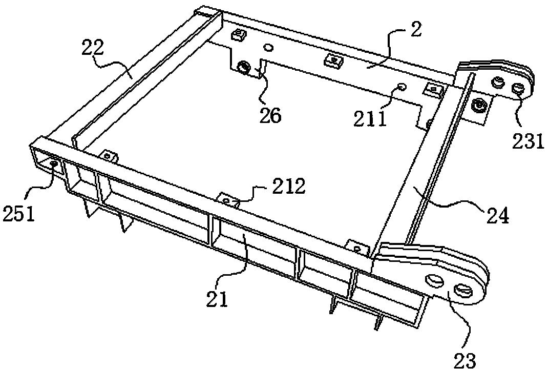
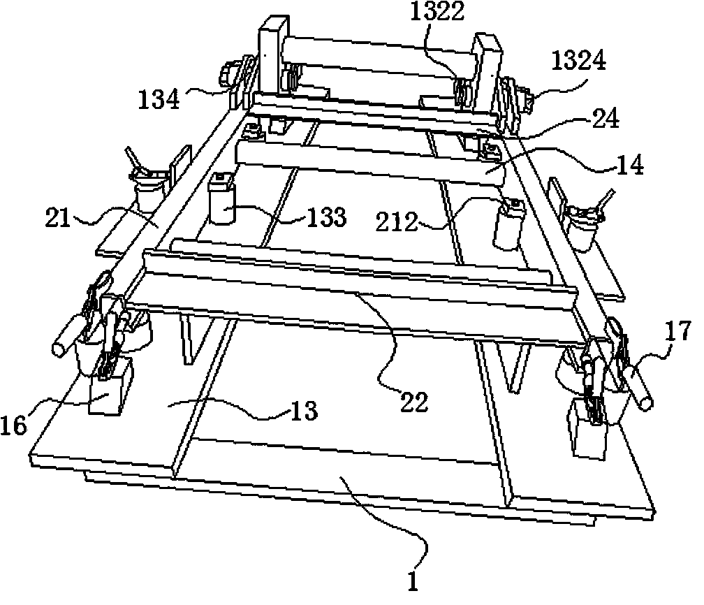
[0020] Such as figure 2 and Figure 4 It shows the structure of the elevator transmission frame, including the fixed frame 21 located on both sides of the transmission frame 2 and the front angle steel 24 and the rear angle steel 22 located on the front and rear sides of the transmission frame 2. A pair of lugs 23 are respectively provided on both sides of the front end of the fixed frame 21, The fixed frame 21 is provided with several connecting blocks 25 arranged along the length direction, and the connecting block 25 is provided with bolt holes B (2121), and a pair of supporting feet 26 are provided under the fixed frame, and the rear end of the fixed frame 21 The lower side is provided with a connecting plate 25, the connecting plate 25 is provided with ...


PUM


Abstract

The invention relates to an elevator transmission frame welding and positioning device. The elevator transmission frame welding and positioning device is characterized by comprising a welding machine base provided with a left side beam and a right side beam, the left side beam and the right side beam are parallel with each other, the upper surface of the left side beam and the upper surface of the right side beam are respectively and fixedly connected with a bottom plate, the bottom plates are located on the same plane, two cross rods are transversely arranged between the left side beam and the right side beam, the two end faces of each cross rod are respectively provided with threaded holes matched with bolt holes in fixed frames on the two sides of a transmission frame, the back side portion of each bottom plate is provided with an L-shaped supporting plate used for positioning back angle iron on the back side of the transmission frame, the front side portion of each bottom plate is provided with vertical fixing plates matched with the inner side faces of lugs on the front side of the transmission frame, the inner side of each fixing plate is fixedly connected with positioning blocks extending out of the back side face of a connecting plate, and the positioning blocks are perpendicular to the back side face of the connecting plate and are used for positioning front angle iron on the front side of the transmission frame. The invention further relates to a corresponding elevator transmission frame welding method.

Description

technical field [0001] The invention relates to a welding positioning device, in particular to a welding positioning device for an elevator drive frame. Background technique [0002] The welding of the existing construction elevator transmission frame is judged by the welder by the naked eye. Even experienced welders will have visual errors, so that the positioning accuracy of each component on the elevator transmission frame obtained by welding is not perfect. However, the welding accuracy of the elevator transmission frame directly affects the normal and safe operation of the construction elevator. The deviation of the welding positioning accuracy makes the operation of the construction elevator a great safety hazard. Contents of the invention [0003] In view of this, the object of the present invention is to provide a welding positioning device for an elevator drive frame that is reliable in positioning and can effectively improve welding efficiency. [0004] The pres...

Claims


Application Information

Patent Timeline
Patent Type & Authority Applications(China)
IPC IPC(8): B23K37/04
CPCB23K37/0435B23K37/0443
Inventor 吴道平金鑫
Owner FUJIAN YOUSHENGDA ELEVATOR
Why Eureka
Try Eureka