
Rail car and side wall assembly thereof

A technology for rail vehicles and side walls, applied in the field of rail vehicles, can solve the problems of inability to form installation parts, stress concentration, narrow width, etc.

Active Publication Date: 2015-12-30
CRRC QINGDAO SIFANG CO LTD
View PDF9 Cites 6 Cited by
  • Summary
  • Abstract
  • Description
  • Claims
  • Application Information

AI Technical Summary

Problems solved by technology

[0007] First of all, the exterior and interior surfaces of the upper and lower edges of the side window installation opening are only supported by the oblique inner ribs inside the profile, which cannot form a flat installation position, and the structural strength is weak. After the side window is installed The stability needs to be further improved
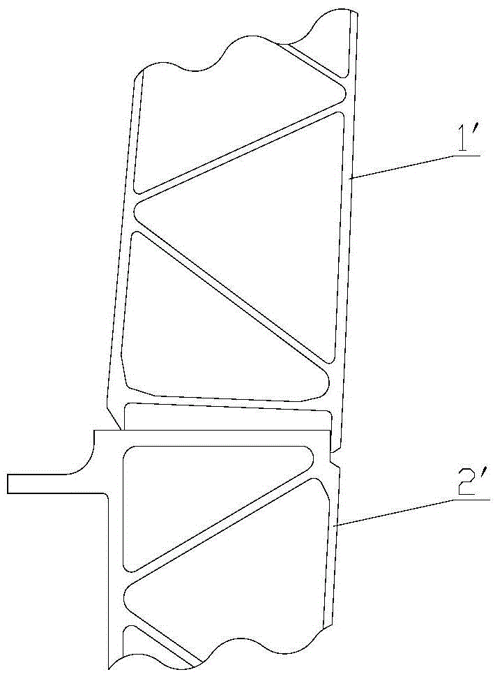
[0008] Secondly, if figure 1 As shown, the welding position of the lower edge of the side wall 1' and the side beam 2' is almost on the same plane as the floor surface, and the joint position is lower, just in the right-angle area where the side wall 1' and the side beam 2' meet. When driving at high speed, under the action of a large internal and external pressure difference, the outside air is easy to penetrate into the interior of the car body along the floor surface, and the airtight load strength is weak
[0009] Furthermore, in order to connect with the side beams, the lower edge of the side wall is generally designed to be wider, while the part above the lower edge is designed to be narrower. The side wall suddenly widens at the lower edge and forms a slope on the inner side. This abrupt cross-section There is a phenomenon of stress concentration in the widened part of the side wall, and the part above the lower edge has a weaker structural strength due to its narrow width

Method used


Image

  • Rail car and side wall assembly thereof
  • Rail car and side wall assembly thereof
  • Rail car and side wall assembly thereof

Examples


Embodiment Construction

[0040] In order to enable those skilled in the art to better understand the solution of the present invention, the present invention will be further described in detail below in conjunction with the accompanying drawings and specific embodiments.

[0041] Terms such as up, down, inside, and outside in this article are established based on the positional relationship shown in the drawings. Depending on the drawings, the corresponding positional relationship may also change accordingly. Absolute limitation of the scope of protection.

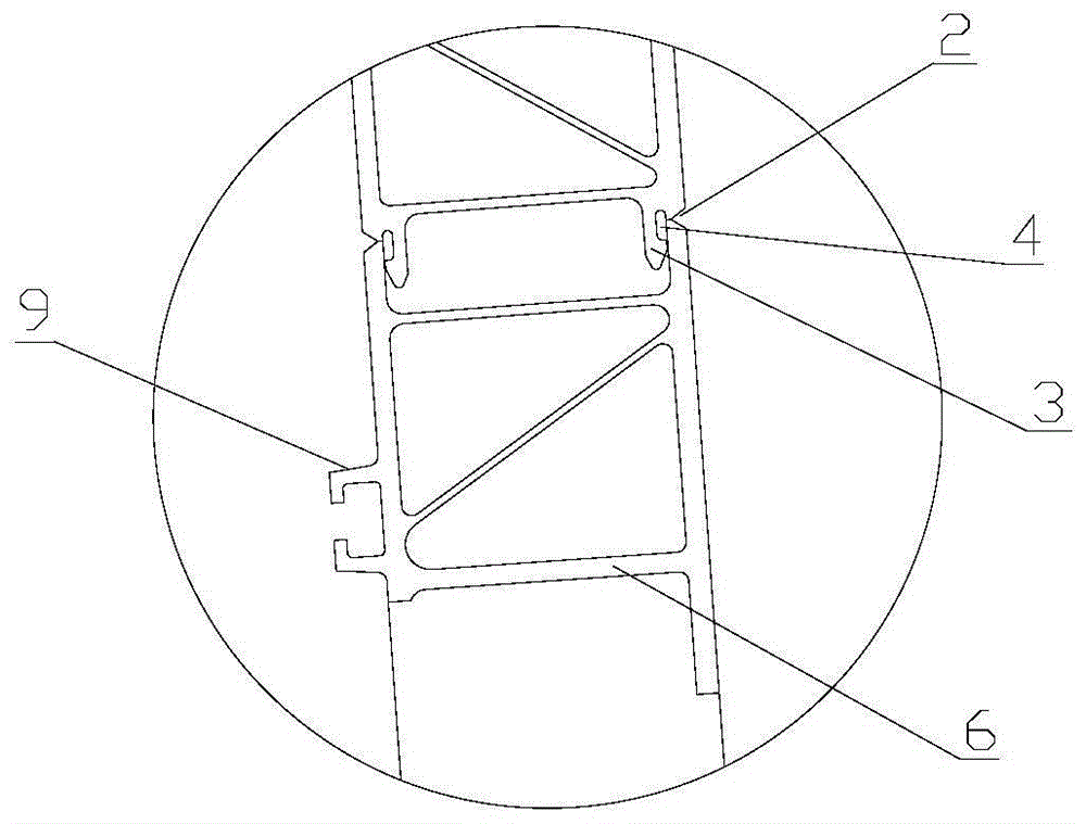
[0042] Please refer to figure 2 , image 3 , figure 2 A schematic cross-sectional view of the side wall assembly provided by the present invention at the opening position of the side window; image 3 for figure 2 Partial enlarged view of part A in the middle.

[0043] In a specific embodiment, the present invention provides a side wall assembly that is strong enough to place air conditioners and other equipment on the roof of a vehicle, an...


PUM


Abstract

The invention discloses a rail car and a side wall assembly thereof. The side wall assembly is formed by inserting and welding a plurality of aluminium alloy extruded sections (1); a car body accessory installation opening is formed in the body of the side wall assembly; a subplate (3) which is formed on one of the two adjacent aluminium alloy extruded sections (1) is arranged at the inner side of a joint of the two corresponding adjacent aluminium alloy extruded sections (1), the subplate (3) is in a hook shape on the section, the head of the subplate (3) is clung to the inner wall of the joint of the other aluminium alloy extruded section (1), and a hook groove between the root and the head of the subplate (3) forms a cavity (4) corresponding to the joint. The side wall assembly is used for optimizing a design of inserting structures and welding structures of the aluminium alloy extruded sections, a local structure of the installation opening, section shapes and the like, so that the structure strength and an air sealing performance of a side wall can be obviously improved, and the side wall assembly can be suitable for a car body structure that devices, such as sliding plug doors and air conditioners are installed onto of a car top.

Description

technical field [0001] The invention relates to the technical field of rail vehicles, in particular to side wall assemblies of rail vehicles. The invention also relates to a rail vehicle provided with said side wall assembly. Background technique [0002] As an integral part of the train, the car body is not only the passenger carrier, but also the basis for installing and linking several other components (such as running parts, braking devices, car end connection devices, vehicle interior decoration equipment, etc.), according to the material It can be divided into three types: weathering steel body, stainless steel body and aluminum alloy body. [0003] The car body is generally composed of the driver's cab (head car, tail car), underframe, roof, side walls, end walls and car body accessories, etc. to form a thin-walled cylindrical overall bearing structure with door and window cutouts. [0004] In order to further realize the lightweight of the car body, modern high-spe...

Claims


Application Information

Patent Timeline
IPC IPC(8): B61D17/08
Inventor 高玉龙赵士忠马乐坤李伟陈文宾聂双双喻海洋户迎灿鄢桂珍陶桂东田爱琴王军
Owner CRRC QINGDAO SIFANG CO LTD
Learn More