joystick assembly

A joystick and assembly technology, applied in the field of construction machinery operating mechanisms, can solve the problems of large control resistance, reduced ability of pipe joints to bear tensile force, deformation of outer pipe steel wires, etc., so as to improve load efficiency and service life, reduce Resistance and idle travel, the effect of solving early wear

Active Publication Date: 2017-05-17
LIUZHOU JINYUAN MACHINERY MFG
View PDF7 Cites 0 Cited by
  • Summary
  • Abstract
  • Description
  • Claims
  • Application Information

AI Technical Summary

Problems solved by technology

The riveting of the pressure-resistant hose and the metal pipe joint in the flexible shaft assembly adopts the punching riveting process, and the upper and lower molds are used for riveting. When punching riveting, only the upper and lower directions generate impact on the metal pipe joint, and the stamping time is short. The rear metal pipe joint quickly deforms into a hexagonal or octagonal shape, which easily deforms the steel wires of the outer pipe and becomes forked, and the distribution is uneven, which reduces the ability of the pipe joint to withstand tensile force, and also causes deformation of the inner hole, and the shaft core is in the working position. Sliding resistance increases during running under normal conditions, and it is easy to cause stagnation and jamming, which makes the control resistance large, and in severe cases, the shaft core will break, resulting in short service life of the push-pull flexible shaft

Method used


Image

  • joystick assembly
  • joystick assembly
  • joystick assembly

Examples


Embodiment 1

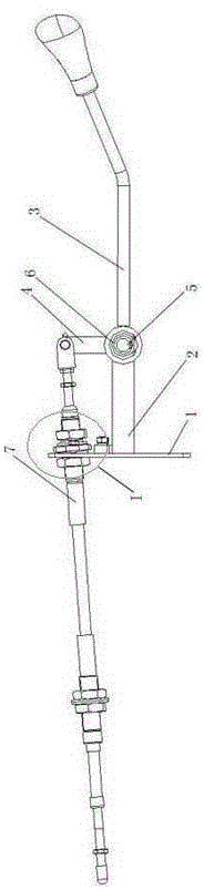
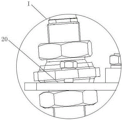
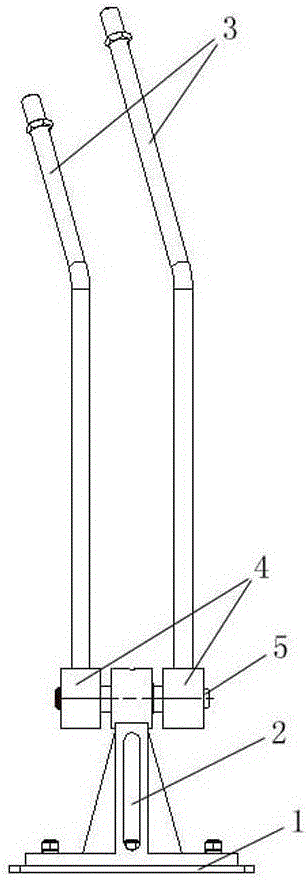
[0024] like Figure 1~Figure 4 As shown, the joystick assembly of this embodiment includes a base 1, a bracket 2, a joystick 3, a rocker arm 4, a main shaft 5, a bearing 6, and a flexible shaft 7. The bracket 2 is fixedly connected to the base 1, and the main shaft 5 Installed on the bracket 2, it is characterized in that: the joystick 3 is fixedly connected to the rocker arm 4, one end of the rocker arm 4 connected to the joystick 3 is connected to the main shaft 5 through a bearing 6, and the flexible shaft 7 is connected to the rocker arm 4 The other end is connected, the other end of the flexible shaft 7 passes through the base 1, and the connection mode between the flexible shaft 7 and the base 1 is a hemispherical hinge;

[0025] The rocking arm 4 is provided with a hole 8 matching with the end of the joystick 3, and the connection mode between the joystick 3 and the rocking arm 4 is: the end of the joystick 3 is matched with the hole 8 of the rocking arm and then welded...


PUM


Abstract

The invention discloses an operating lever assembly. The operating lever assembly comprises a pedestal, a bracket, an operating lever, a rocker, a spindle, a bearing and a flexible shaft, wherein the bracket is firmly connected with the pedestal; the spindle is mounted on the bracket; the operating lever is firmly connected with the rocker; the end of the rocker connected with the operating lever is connected with the spindle through the bearing; the flexible shaft is connected with the other end of the rocker; the other end of the flexible shaft passes through the pedestal; the flexible shaft is in semi-sphere hinge to the pedestal. According to the invention, an operating mechanism and the push-pull flexible shaft are integrated into one module in the operating mechanism assembly, so that the assembly cost is lowered, and the assembly matching problem is solved; and meanwhile, the all-directions round buckle riveting technique is used for reinforcing the pulling-out force of the joints, so that the service life is guaranteed; a pressure-resistant hose is matched with the multilayer structure of a central spindle, so that the resistance and the idle running are reduced.

Description

technical field [0001] The invention relates to an engineering machinery operating mechanism, in particular to an operating rod assembly. Background technique [0002] At present, the operating mechanism of construction machinery is usually divided into the design of the joystick and the flexible shaft assembly, which are assembled and formed after manufacture. Therefore, manpower is required for the assembly process. At the same time, there may be problems with the quality of assembly and fit, which increases assembly costs. . The riveting of the pressure-resistant hose and the metal pipe joint in the flexible shaft assembly adopts the punching riveting process, and the upper and lower molds are used for riveting. When punching riveting, only the up and down direction produces impact on the metal pipe joint, and the stamping time is short. The rear metal pipe joint quickly deforms into a hexagonal or octagonal shape, which easily deforms the steel wires of the outer pipe a...

Claims


Application Information

Patent Timeline
Patent Type & Authority Patents(China)
IPC IPC(8): B60K20/02B60T7/10F16H59/02
Inventor 邓加尊黄晓练马春文
Owner LIUZHOU JINYUAN MACHINERY MFG
Why Eureka
Try Eureka