Belt pulley runout detecting tool

A technology of jump detection and pulley, which is applied in the direction of measuring device, mechanical measuring device, and mechanical device, etc., can solve the problems of large size error of pulley, reduced belt life, skewed groove shape of pulley, etc., so as to ensure the use effect and The effect of longer life, increased sampling ratio, and low manufacturing cost

Inactive Publication Date: 2014-04-30
ZHEJIANG RIFENG MACHINERY
View PDF5 Cites 10 Cited by
  • Summary
  • Abstract
  • Description
  • Claims
  • Application Information

AI Technical Summary

Problems solved by technology

[0002] At present, when processing the pulley, the first thing is to use a single knife-angle template or a universal vernier angle ruler to verify the sharpening tool. The verticality of the center of the knife-shaped angle bisector of the tool clamping is usually determined by visual inspection. Due to the above-mentioned processing Due to the particularity of the process, the processed pulley grooves are prone to skewed and irregular shapes, resulting in large size errors of the pulley. The belt is easy to slip and the transmission is not stable during use, which greatly reduces the life of the belt.
At present, the runout detection is to use the pointer of the dial indicator to measure the runout of one side of the wheel groove on the deflection meter. The detection efficiency of the method is low, the detection accuracy is low, it is difficult to control the quality during the incoming inspection, and it is impossible to ensure that the quality of the pulley meets the design requirements, so the service life of the pulley cannot be guaranteed
So far, there is no special tool for detecting whether the radial runout of the pulley groove, the axial runout of the pulley groove, and the runout of the end face of the pulley meet the standards

Method used


Image

  • Belt pulley runout detecting tool
  • Belt pulley runout detecting tool
  • Belt pulley runout detecting tool

Examples


Embodiment 1

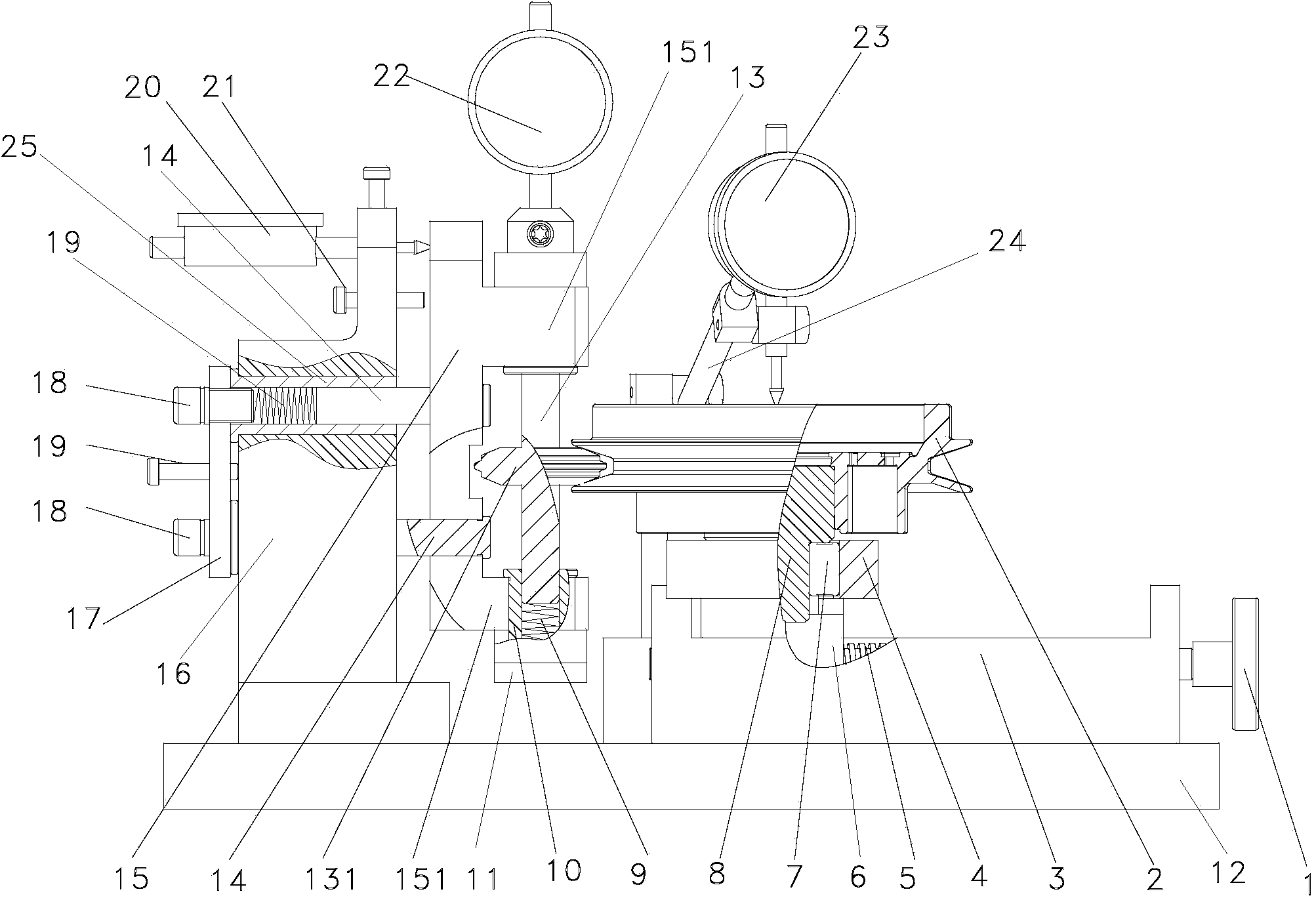
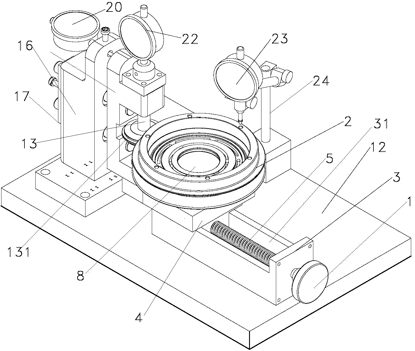
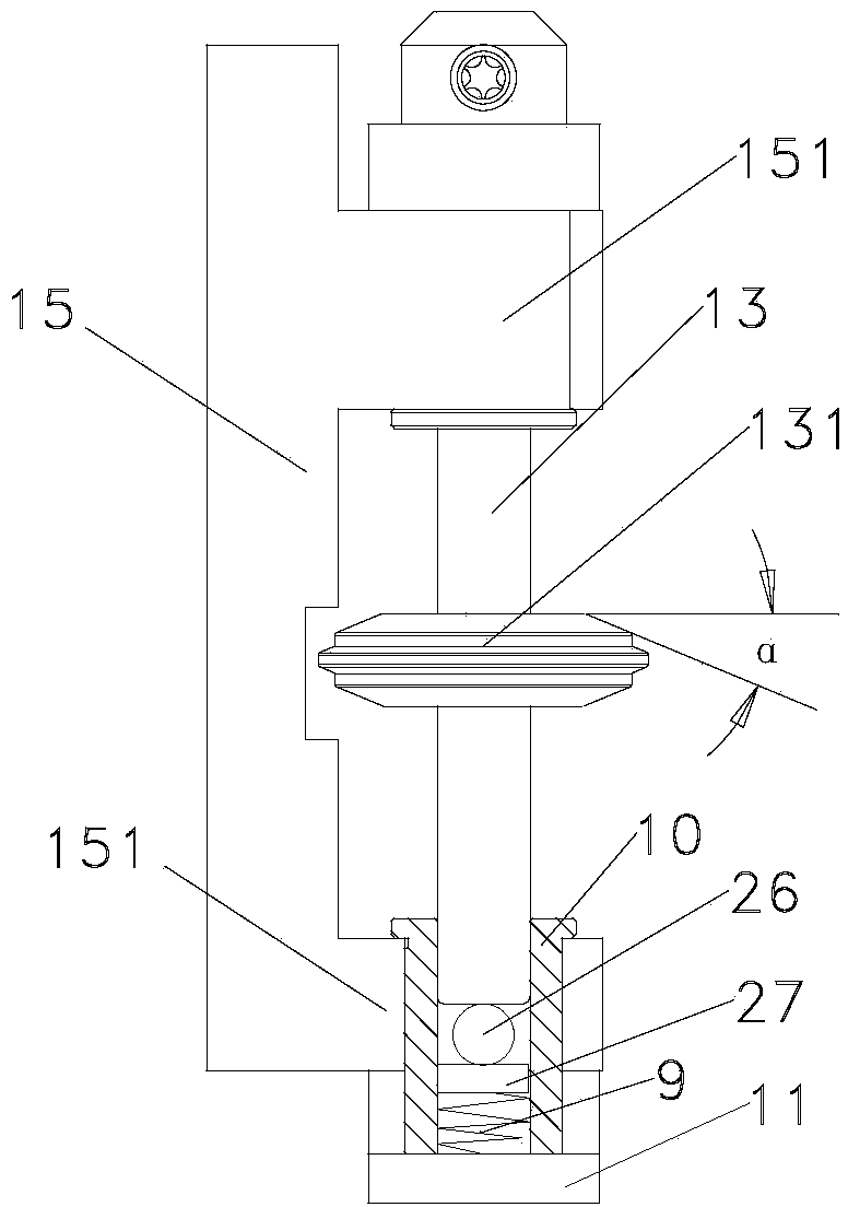
[0013] Example 1: Reference Figures 1 to 3 . A pulley runout detection tool includes several dial indicators, a base 12, a fixed seat 3, a screw rod 5, a handwheel 1, a sliding seat 6, a positioning shaft 8, a guide shaft 14, a floating bracket 15, and a fixed bracket 16. A fixing bracket 16 is arranged on the left side above the seat 12, and a fixing seat 3 is arranged on the right side. The fixing seat 3 is provided with a chute 31 with an upward opening. 5. The left end is connected to the left groove wall of the fixed seat 3, and its right end protrudes from the right groove wall of the fixed seat 3 and is connected to the center of the handwheel 1 outside the right end of the fixed seat 3. The lower end of the sliding seat 6 extends into the chute 31 and It is connected with the horizontal guide of the screw 5, and the front and rear sides of the lower end of the sliding seat 6 are respectively connected with the front and rear groove walls of the chute 31. The upper en...


PUM


Abstract

The invention relates to a belt pulley runout detecting tool which comprises a plurality of dial indicators, a base, a fixing seat, a lead screw, a hand wheel, a sliding seat, a positioning shaft, a guide shaft, a floating support, a fixed support and a measuring shaft. The first dial indicator is arranged outside a shaft seat at the upper end of the measuring shaft, the measuring end of the first dial indicator is in axial connection with the upper end of the measuring shaft, and the indicator body end of the first dial indicator is fixedly connected with the shaft seat. The second dial indicator is arranged at the upper end of the fixed support, the measuring end of the second dial indicator is connected with the left side of the floating support, and the indicator body end of the second dial indicator is fixedly connected with the fixed support. The third dial indicator which is connected with the base through the support is arranged on one side above the positioning shaft. The second dial indicator is used for detecting radial runout of a belt pulley, the first dial indicator is used for detecting axial runout of the belt pulley, and the third dial indicator is used for detecting end face runout of the belt pulley.

Description

technical field [0001] The invention relates to a detection tool, in particular to a pulley runout detection tool. Background technique [0002] At present, when processing the pulley, the first is to use a single blade angle template or a universal vernier angle ruler to check the sharpening tool. Due to the particularity of the process, the processed pulley grooves are prone to the phenomenon of skewed grooves and irregular shapes, resulting in large size errors of the pulleys. At present, the runout detection is to measure the runout of the wheel groove on one side with the dial indicator pointer on the yaw meter. The method has low detection efficiency and low detection accuracy. It is difficult to control the quality during incoming inspection, and it is impossible to ensure that the quality of the pulley meets the design requirements, so it cannot guarantee the service life of the pulley. So far, there is no special tool for detecting whether the radial runout of the...

Claims


Application Information

Patent Timeline
Patent Type & Authority Applications(China)
IPC IPC(8): G01B5/00
Inventor 万国勇黄少林黄臣徐鑫
Owner ZHEJIANG RIFENG MACHINERY
Why Eureka
Try Eureka